 |
Introduction
Details, details! Versatile drafting Help when you need it Nuts and bolts Spectacular views Easy does it Crank it up SI Mechanical Parametric Database Drawing Formats Hardware |
SI Mechanical offers a wide range of productivity tools and annotation capabilities for mechanical engineers, designers, and drafters working with AutoCAD. With SI Mechanical you can create part and assembly drawings that automatically conform to ASME (American Society of Mechanical Engineers), ANSI (American National Standards Institute), ISO (International Standards Organization), and other international standards. Both inch and System International (SI) metric units are supported. These standards are built into SI Mechanical, eliminating the chore of setting routine variables such as layers, scales, and text height. You will complete higher quality drawings in less time. Companies can achieve a new level of drawing consistency among individuals and departments. New AutoCAD users can now be productive almost instantly by using SI Mechanical to help create mechanical drawings. Whether you are an experienced AutoCAD user or just starting out, you can save time and money with SI Mechanical.
Setting up a drawing with SI Mechanical couldn't be easier. SI Mechanical contains all standard ASME, DIN, JIS, and ISO drawing formats (100's of different types). You can also instruct SI Mechanical to use your custom formats. With SI Mechanical you will feel at home using either model space or paper space, 2D or solids. You can set your drawing up to any size and scale and SI Mechanical will handle your layering, placement of title block information, text sizes, dimension sizes, hatch scales, and line scales. Multiple sheet drawings, or entire projects can be setup in a single drawing file or seperate files.
You can select ASME or ISO standards and inch, mm, or any other unit you wish. All of your hardware and other symbols are always sized correctly.
SI Mechanical uses a rule based symbol generator for all geometric tolerancing, surface finish and welding symbols. We have consulted with industry experts to create the table of rules for our geometric tolerancing. When you create or edit a symbol, the rules are automatically applied, ensuring every symbol you create is valid and conforms to standards. And, the symbols respond to dimension variables.
With SI Mechanical, you can forget about having to use the manual. On line, context sensitive help is always available in one pick. Need additional information about a command? Push the button for instant help. SI Mechanical is open. The database editor allows you to customize all aspects of the program to work the way you want. Even the Program Interface is documented so you can write your own routines to access SI Mechanical functions and database tables.
 |
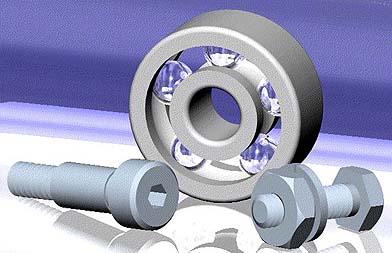
Insert a bolt in fast 2D or wire frame
view. Change it to a solid. Add detailed threads.
Increase its length. Change its size. Change it to a cap
screw. Change it back. It's easy with SI Mechanical. Try
that with a typical symbol library. Create an unlimited
number of unique pieces of hardware without touching the
keyboard. SI Mechanical creates hundreds of different
types, in any view, in dozens of different sizes and
lengths, with only one command. Since SI Mechanical creates the hardware from an ASCII database of tables, it doesn't waste hard disk space. Also, you can edit and expand the tables to contain custom sizes |
You will not be restricted to a limited selection of 3D hardware. All of the hardware that you create with SI Mechanical can be displayed as a 2D view, 3D wire frame, or true solid. Even 2D isometric views of all components are available.You can work in wire frame mode for speed and keep your drawing files small. You can also work in solids or automatically convert any one or all 2D and wire frame hardware in your drawing to solids. When combined with the rendering capabilities of AutoCAD, you can create realistic images of your drawings. Things that used to take hours are now done in minutes. The power and flexibility of SI Mechanical allows you to work the way you like in record time.
The dialogue boxes in SI Mechanical make it easy to create and edit hardware, holes, shafts, and symbols. We challenge you to compare it with any other program. SI Mechanical can't be beat for flexibility, thoroughness, and ease of use.
SI Mechanical's layer facility will handle layering for you. It includes standard layers ready to use. You already have your own layering scheme? No problem. You can easily create new layer control files so that SI Mechanical will automatically use the layering scheme you specify. For complete flexibility, you can set it to use the current drawing layer.
SI Mechanical commands can be accessed from your own menu or from the keyboard. Also, SI Mechanical commands can use aliases so you can create even more shortcuts to productivity.
 |
The shaft generator lets you create parametric, feature based parts with ease. Create crank shafts, gears, pipe flanges, pulleys, sprockets, or any other turned part you can think of. Create one part and then just change the dimensions to create a new one. You can add and remove features such as snap ring grooves, holes, keyways, offsets, recesses, tapers, threads, and many more. You tell it what you want and SI Mechanical does the work. |
Hardwareaircraft bolt |
oval head, Type
IA oval head, Type II oval head, slotted oval head, trim, Type I oval head, trim, Type IA oval head, trim, Type II oval head, UC, Type I oval head, UC, Type IA oval head, UC, Type II oval head, UC, slotted PEM B, blind fastener PEM BS, blind fastener PEM BSO, blind standoff PEM BSOA, blind standoff PEM BSOS, blind standoff PEM CLS, nut PEM CLSS, nut PEM F, flush nut PEM FH, flush HD stud pin PEM FH, flush HD stud PEM FHA, flush HD stud pin PEM FHA, flush HD stud PEM FHN, flush HD stud pin PEM FHS, flush HD stud pin PEM FHS, flush HD stud PEM S, nut PEM SO, standoff PEM SO, unthreaded standoff PEM SOA, standoff PEM SOA, unthreaded standoff PEM SOS, standoff PEM SOS, unthreaded standoff PEM SS, nut PEM TFH, non-flush HD stud PEM TFHS, non-flush HD stud pipe plug pan head, Type I pan head, Type IA pan head, Type II pan head, cross, DIN 7985A pan head, slotted pan head, slotted, DIN 85A roller bearing round head, Type I round head, Type II round head, slotted socket head cap screw, DIN 912 socket head cap screw socket head cap screw, DIN 7984A shoulder screw square nut set screw, slotted, 1/2 dog point set screw, slotted, cone point set screw, slotted, cup point set screw, slotted, flat point set screw, hex, 1/2 dog point set screw, hex, cone point set screw, hex, DIN 914 set screw, hex, cup point set screw, hex, DIN 916 set screw, hex, DIN 915 set screw, hex, flat point set screw, hex, DIN 913 set screw, slotted, DIN 553 set screw, slotted, DIN 551 set screw, spline, 1/2 dog point set screw, spline, cone point set screw, spline, cup point set screw, spline, flat point structural angle structural C-channel structural I-beam structural T-section tapered roller bearing thrust bearing truss head, Type I truss head, Type IA truss head, Type II truss head, slotted plus more |
Holesblind and through holes Shaft featureschamfers Drawing setupautomated dimension sizing Drawing annotationautomatic datum dimensioning Utilitiescontext sensitive help facility |
AutoCAD R13C4a, R14, 2000, AutoCAD Mechanical Desktop, Windows 95 or Windows NT. Other versions available for AutoCAD R12, R13, DOS and Windows
| Design Pacifica |