The Zero option lets you reset the UCS origin to a new zero point location.
Command: xydim
Exit/Xdim/Ydim/Zero/<default>: z
Indicate zero point: Pick point.

AXYDIM Command
The AXYDIM (Automatic X Y DIMension) command runs XYDIM in an automatic mode, and allows you to dimension a drawing by picking items to dimension as a group. AXYDIM then decides how to place the dimensions in the drawing and does it for you.Command: axydim
Indicate Zero point <options>:
Select objects: Do so.
Indicate X dimension location: Pick point.
Indicate Y dimension location: Pick point.
If you press [Enter] instead of indicating a zero point, a dialogue box will be displayed allowing you to specify certain types of entities and dimension options before starting the automatic dimensioning.
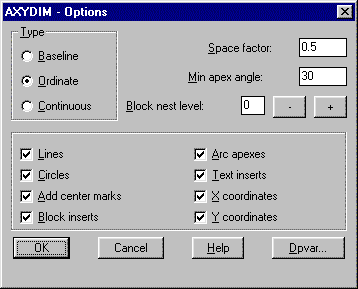
- Type
- This group of buttons set the type of dimensions that AXYDIM will draw.
- Space factor:
- This edit box sets the relative spacing between dimensions. A value of 0.5 would leave at least half the dimension text height between each dimension.
- Min apex angle:
- This edit box sets the minimum apex angle to use when dimensioning to arc apexes. If you have angled sides with fillets on the corners, the corners will be dimensioned as long as they meet the minimum apex angle setting.
- Block nest level
- This group sets how deep to go into blocks to obtain entities to dimension. If the item is a block, and you want the items inside the block to be dimensioned, set it to 1. When the items inside the block are nested blocks, you must set the number higher to dimension items inside the nested blocks. The higher the setting the deeper it will go into the nested blocks.
- Lines
- This check box sets AXYDIM to dimension to line endpoints.
- Circles
- This check box sets AXYDIM to dimension to circle center points.
- Add center marks
- This check box sets AXYDIM to add center marks to each circle that it dimensions to.
- Blocks inserts
- This check box sets AXYDIM to dimension to block insert points.
- Arc apexes
- This check box sets AXYDIM to dimension to the intersection of the two tangencies of arc endpoints.
- Text inserts
- This check box sets AXYDIM to dimension to text insert points.
- X coordinates
- This check box sets AXYDIM to draw X coordinate dimensions.
- Y coordinates
- This check box sets AXYDIM to draw Y coordinate dimensions.
XYTABLE Command
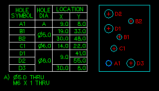
The XYTABLE (X Y TABLE) command draws a table of sizes and X and Y coordinates of selected circles and hole items in a drawing. The circles and holes are grouped in the chart by size, X coordinate, and Y coordinate, in ascending order. Circle sizes are included inside the chart while hole descriptions are placed just below the chart. The hole descriptions are identical to those produced by the LABEL command.Command: xytable
Indicate zero point <options>:
Select objects: Do So.
Upper left corner of table: Pick point.
If you press [Enter] instead of indicating a zero point, a dialogue box will be displayed allowing you to control center marks and hole symbol markers.
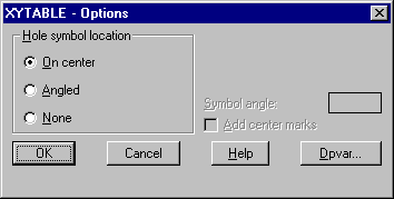
- On center
- This button places the hole symbols at the circle center point
- Angled
- This button places the hole symbol just outside the circle radius at the specified angle from the center.
- None
- This button indicates that no hole symbols will be drawn.
- Symbol angle:
- This edit box sets the angle for hole symbols. The value indicates the angle of an imaginary line between the circle center and the hole symbol.
- Add center marks
- This check box sets XYTABLE to draw center marks on all circles.
All valid entities in the selection set will be processed and a table will be drawn.
See the following DPVAR variables that directly affect the XYDIM, AXYDIM, and XYTABLE commands: