Parametric Hardware
This section covers the HARDWARE, HOLE, and SHAFT commands. They are
used for part creation as opposed to drawing annotation.
ITEMODES Command
The ITEMODES command is used to set options that affect hardware,
hole, and shaft items.
Command: itemodes
A dialogue box similar to the following figure is displayed:
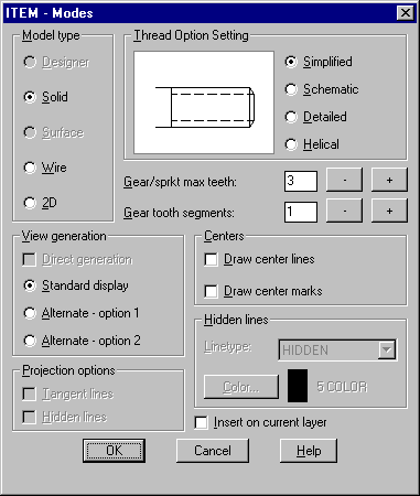
When a button is grayed out, it indicates that the option is not available
for that particular item.
- Model type
- This group of buttons sets the model type
for item creation.
- Designer
- This button specifies creation of a Designer
item. Designer must be loaded to use this option. Unless you intend
to modify the part using Designer, Solid is
the more efficient setting.
- Solid
- This button specifies creation of a solid
item.
- Wire
- This button specifies creation of a wire frame
model. When combined with Direct generation,
this is the fastest and most efficient 3D model option.
- 2D
- This button specifies creation of 2D models.
- View generation
- This group includes a Direct generation toggle
and a set of buttons to set the ITEMALTD
DPVAR variable. Standard display, Alternate
- option 1, and Alternate - option 2
indicate a setting of 0, 1, or 2. Only some items are affected by
this setting. For instance, a clip can be drawn in either an open
or closed position.
- Direct generation
- This toggle sets the ITEMGEN DPVAR variable.
It indicates direct creation of 2D and wire frame models when possible.
If toggled off, all 2D and wire frame items are created by solid projection.
- Projection options
- This pair of toggles sets options for projected
items.
- Tangent lines
- This toggle sets the ITEMTAND
DPVAR variable. It indicates that tangent lines will be drawn on projected
items. For instance, an edge that shows the transition between a fillet
and a straight side can be displayed or not.
- Hidden lines
- This toggle sets the ITEMHIDLIN
DPVAR variable. It indicates that hidden lines will be drawn on projected
items.
- Thread Option Setting
- This group of buttons sets the THREAD
DPVAR variable. It controls the display of threads in most instances.
- Simplified
- This button set the threads to a simplified
representation for 2D views and wire frame models. This is the fastest
and most efficient setting. Solids are created as a straight shank
or hole at the nominal thread diameter.
- Schematic
- This button sets the threads to a schematic
representation for 2D views. It applies to external threads only.
- Detailed
- This button sets the threads to a detailed
representation for 2D and solids. It does not apply to internal 2D
threads. The threads are represented as angled lines on 2D views.
Solids are created with annular threads.
- Helical
- This button sets the threads to a helical
representation for 2D direct views. It applies to external threads
only. It is much less efficient than detailed threads and gives little
additional information. Solid threads cannot be helical.
When a thread setting is not supported by the current view, it will
revert to the next simpler setting.

- Gear/sprkt max teeth:
- This group sets the TOOTHMAX
DPVAR variable. It controls the maximum number of teeth that will
be displayed on gears and sprockets. When drawing solid items with
a large number of teeth, a high value will cause slow generation.
When set to a low number such as 3 for instance, only three teeth
will be displayed, regardless of the actual number of teeth on the
gear or sprocket.
- Gear tooth segments:
- This group sets the TOOTHSEG
DPVAR variable. It controls the accuracy of gear teeth. A setting
of 1 is adequate for drawings. If you intend to cut teeth directly
from the drawing file, then a higher setting is required. Gears with
a low number of teeth require a higher setting to maintain accuracy.
A higher setting results in slower generation.
- Centers
- This group sets the ITEMCTRL
and ITEMCTRM DPVAR variables to control
center lines and center marks on items.
- Linetype:
- This pop-up list sets the ITEMLTYPEH
DPVAR variable. It controls the linetype used for hidden lines. Any
linetype defined in the current drawing can be selected.
- Color...
- This button displays the color dialogue box
and sets the ITEMCLRH DPVAR variable.
It controls the color used for hidden lines.
- Insert on current layer
- This toggle sets the ITEMCLYR
DPVAR variable. When checked, items will be inserted on the current
layer. Otherwise they are inserted on the layer defined in the SI Mechanical
layer map table.
View Orientation
The HARDWARE, HOLE, and SHAFT commands create items that represent
physical features
or objects. They can be created in a variety of views relative to
your current drawing coordinate system. A group in the dialogue box
containing a pop-up list sets the orientation. The group will be similar
to the following figure:
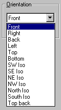
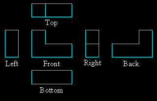
- Front
- This setting specifies creation of a front,
orthogonal view. Sometimes called the plan view, it looks down a hole
or shows the plan view of an item such as a screw head.
- Right
- This setting specifies creation of a right
side orthogonal view. It shows the entire length of a hole or item
such as a screw.
- Back
- This setting specifies creation of a back
orthogonal view. It shows the underside of an item such as a screw
head. For items like washers, the front and back views are the same.
- Left
- This setting specifies creation of a left
side orthogonal view.
- Top
- This setting specifies creation of a top orthogonal
view.
- Bottom
- This setting specifies creation of a bottom
orthogonal view.
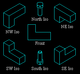
- SW Iso
- This setting specifies creation of a southwest
isometric view.
- SE Iso
- This setting specifies creation of a southeast
isometric view.
- NE Iso
- This setting specifies creation of a northeast
isometric view.
- NW Iso
- This setting specifies creation of a northwest
isometric view.
- North Iso
- This setting specifies creation of a north
isometric view. The item is tipped forward at an angle. An example
would be a bolt projecting down into an assembly.
- South Iso
- This setting specifies creation of a south
isometric view. The part is upside down and tipped forward at an angle.
An example would be a bolt projecting up into an assembly.
- Top back
- This is another back view rotated 90 degrees
as projected from the top view.
HARDWARE Command
The HARDWARE command creates a variety of items from parametric data.
There are many types and sizes available. All can be represented as
a 2D view or 3D model.
Command: hardware
2D, Front, ISO 4017, M6 X 1
Insert point <options>: Pick point.
<Rotation angle>/Reference: Pick point or type angle.
The command line shows the current hardware settings. The settings
can be changed by responding with [Enter] to the insert point prompt.
A dialogue box similar to the following figure will be displayed:
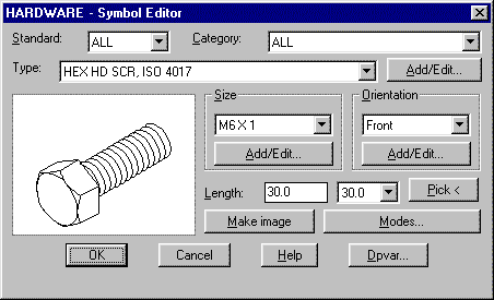
- Standard
- This pop-up list is the primary search criteria
for hardware and is based on standards. All available categories in
the selected standard will be displayed in the Category pop-up list.
- Category
- This pop-up list is the is the secondary search
criteria for hardware and is based on category. All available items
in the current hardware standard and selected category will be displayed
in the Type pop-up list.
- Type
- This pop-up list is used to select the type
of hardware to draw. The list contains a description of each item.
After picking an item, a picture of it is shown in the box below the
pop-up list.
- Add/Edit...
- This button displays the Edit Row dialogue
box for the current hardware type record in the hardware table.
- Size
- This group contains a pop-up list to set the
size of the current hardware type.
- Add/Edit...
- This button displays the Edit Row dialogue
box for the current size record in the hardware item table.
- Orientation
- This group contains a pop-up list to set the
orientation of the item to be inserted.
- Add/Edit...
- This button displays the Edit Row dialogue
box for the current orientation record in the view table.
- Length:
- This group contains a combination edit box
and pop-list to specify the length of the hardware.
- Pick <<
- This button temporarily hides the dialogue
box so that the length can be indicated graphically.
- Make image
- This button creates a separate slide image
of the current item to display in the hardware dialogue box. The image
from the slide library is normally displayed. If the button is grayed
out, a new slide is already being displayed, and you must erase the
slide in order to replace it.
- Modes...
- This button displays the ITEMODES dialogue
box to configure how items are created.
The SYMCHG command can be used to change the hardware item at a later
time. See the SYMCHG and SYMUPD commands for more information.
The symbols are created as a single entity. If the symbol is exploded
it reverts back to the base entities. Once a symbol has been exploded
it cannot be edited with SYMCHG or SYMUPD.
See the following DPVAR variables that directly affect the HARDWARE
command.
HDWCSKH,
HDWPEME,
HDWTYPE,
ITEMALTD,
ITEMCLYR,
ITEMCLRH,
ITEMCTRL,
ITEMCTRM,
ITEMDSPL,
ITEMGEN,
ITEMSIZE,
ITEMHIDLIN,
ITEMTAND,
ITEMVIEW,
THREAD,
TOOTHMAX,
TOOTHSEG,
UNIT
HOLE Command
The HOLE command creates holes from parametric data. Various combinations
of features in all standard sizes can be created. All can be represented
as a 2D view or 3D model.
Command: hole
Solid, Front, MM-STD, M6 X 1, Drill depth: 20.0
Insert point <options>: Pick point.
An additional rotation angle prompt is presented when the ITEMVIEW
DPVAR variable is set to 4 (right view) or one of the other side views.
<Rotation angle>/Reference: Pick point or type angle.
If the DRILLDIST DPVAR variable is negative,
an additional prompt is presented:
Through point: Pick point.
The command line shows the current hole settings. The settings can
be changed by responding with [Enter] to the insert point prompt.
A dialogue box similar to the following figure will be displayed:
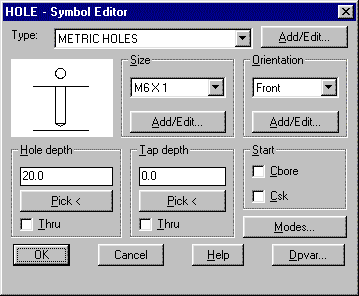
- Type
- This pop-up list is used to select the type
of hole to draw. The list contains a description of each item.
- Add/Edit...
- This button displays the Edit Row dialogue
box for the current hole type record in the hardware table.
- Size
- This group contains a pop-up list to set the
size of the current hole type.
- Add/Edit...
- This button displays the Edit Row dialogue
box for the current size record in the hole item table.
- Orientation
- This group contains a pop-up list to set the
orientation of the item to be inserted.
- Add/Edit...
- This button displays the Edit Row dialogue
box for the current orientation record in the view table.
- Hole depth
- This group contains an edit box to specify
the hole depth, a pick button to graphically indicate the depth, and
a check box to set it to a through hole. The picture in the dialogue
box will display these features.
- Tap depth
- This group contains an edit box to specify
the tap depth, a pick button to graphically indicate the depth, and
a check box to set it to a through tap. A depth value of 0.0 indicates
no tap. The picture in the dialogue box will display these features.
- Pick <
- These buttons temporarily hide the dialogue
box so that a value can be indicated graphically.
- Start
- This group contains two check boxes to set
counterbore, countersink,
or both. The picture in the dialogue box will display these features.
- Modes...
- This button displays the ITEMODES dialogue
box to configure how items are created.

The SYMCHG command can be used to change the hole at a later time.
See the SYMCHG and SYMUPD commands for more information.
The symbols are created as a single entity. If the symbol is exploded
it reverts back to the base entities. Once a symbol has been exploded
it cannot be edited with SYMCHG or SYMUPD.
See the following DPVAR variables that directly affect the HOLE command.
DRILLANG,
DRILLDIST,
DRILLM,
HOLESTART,
HOLETYPE,
ITEMALTD,
ITEMCLYR,
ITEMCLRH,
ITEMCTRL,
ITEMCTRM,
ITEMDSPL,
ITEMGEN,
ITEMSIZE,
ITEMHIDLIN,
ITEMTAND,
ITEMVIEW,
TAPDIST,
THREAD,
UNIT
HOLECLIP Command
The HOLECLIP command is used on holes to clip the end of a thru hole
at an angle.
Command: holeclip
Select item to clip: Do so.
Endpoint of hole: Pick point.
Clip angle: Pick point or type angle.

The endpoint of the hole should be the intersection of the hole center
line and a line representing the edge of the material.
Holes can also be clipped by setting the HOLEEANG
DPVAR variable and then updating the items with the SYMUPD
command. Subsequently drawn thru holes will be clipped according to
the value of HOLEEANG. For instance, if you set HOLEEANG to 45, the
end of thru holes will be drawn with a 45 degree exit angle.
ITEMCLIP Command
The ITEMCLIP command clips or trims hardware, hole, and shaft items.
It is normally used on 2D side views. It is used on hardware to hide
a portion that would be covered by other items. The following prompt
sequence is presented:
Command: itemclip
Select item to clip: Do so.
Start of clip <insert point>: Pick point.
End of clip: Pick point.
If you press [Enter] instead of picking a start
point, the clip will start at the insert point of the item. The clipped
region can be completely blanked out or it can be shown as hidden
lines. The display mode of the clipped region is controlled with the
CLIPHID DPVAR variable.

You can use the SYMUPD command to restore items to an unclipped state.
See the following DPVAR variables that directly affect the ITEMCLIP
command.
CLIPHID
ITEMCLRH
SHAFT Command
The SHAFT command creates an infinite variety of shafts, including
optional features. Features include chamfers, fillets, flats, gears,
grooves, hardware, holes, keyways, offsets, pulleys, recesses, shafts,
spheres, splines, sprockets, and threads. A units feature controls
the relative scale of the shaft. Shafts can be represented as 2D views
or 3D models.
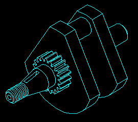
Command: shaft
Solid, Front, 3 segment(s), 1 feature(s)
Insert point <options>: Pick point.
<Rotation angle>/Reference: Pick point or type angle.
The command line shows the current shaft settings. The settings can
be changed by responding with [Enter] to the insert point prompt.
A dialogue box similar to the following figure will be displayed:
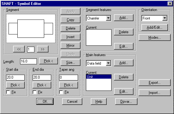
- Segment
- This group contains a schematic of the defined
shaft with the current segment highlighted. A diagonal cross in a
segment indicates features are present on the segment. An edit box
and direction arrows set the current shaft segment.
- Apply
- This button applies previously copied segment
dimensions to the current segment.
- Copy
- This button copies the current segment dimensions
to memory.
- Delete
- This button deletes the current segment.
- Insert
- This button inserts another segment identical
to the current segment.
- Mirror
- This button mirrors the current segment if
it is not symmetrical. Dimensions are mirrored, but features are not.
- Undo
- This button will undo the last segment operation.
- Length:
- This edit box specifies the length of the
current segment. You can also use the associated pick button.
- Pick <<
- These buttons temporarily hide the dialogue
box so that a value can be indicated graphically.
- Size...
- This button displays the Hardware dialogue
box. The selected hardware item will be used to set the size of the
current shaft segment. In this way, the segment can be sized to fit
a bearing, clip, seal, or any other item.
- Start dia
- This group contains an edit box, pick button,
and toggle. The edit box and pick button are used to specify the start
diameter of the segment. The toggle is used to temporarily lock in
the value so that it will not change automatically.
- End dia
- This group contains an edit box, pick button,
and toggle. The edit box and pick button are used to specify the end
diameter of the segment. The toggle is used to temporarily lock in
the value so that it will not change automatically.
- Taper ang
- This group contains an edit box, pick button,
and toggle. The edit box and pick button are used to specify the taper
angle of the segment. The toggle is used to temporarily lock in the
value so that it will not change automatically.
- Orientation
- This group contains a pop-up list to set the
orientation of the item to be inserted.
- Add/Edit...
- This button displays the Edit Row dialogue
box for the current orientation record in the view table.
- Modes...
- This button displays the ITEMODES dialogue
box to configure how items are created.
- Export...
- This button displays the standard file dialogue
box so that you can indicate a file name. The shaft definition will
be written to the specified sft file. Saved shaft definitions
can be used to create compact libraries of user-defined parametric
parts to use in other drawings.
- Import...
- This button displays the standard file dialogue
box so that you can indicate a file name. The file must be an sft
file.
Features
Main and segment features appear as lists in the shaft dialogue box.
Features can be applied on all views, but direct 2D and wire frame
views will not display most features.
- Main features
- This group contains a popup list of available
features that can be applied to the entire shaft.
- Segment features
- This group contains a popup list of available
features that can be applied to the current shaft segment.
- Current
- These two list boxes show the features that
have been applied to the shaft and the shaft segment.
- Add...
- These two buttons display the appropriate
dialogue box to add a feature to the shaft or shaft segment.
- Delete
- These two buttons delete the indicated feature
from the shaft or shaft segment.
- Edit...
- These two buttons display the appropriate
dialogue box to edit a feature of the shaft or shaft segment.
Some features are mutually exclusive. When they are added, other features
may not be used in conjunction with them and will not appear in the
feature list.
Common Feature Options
Many of the features will have similar options that have the same
affect on the individual features.
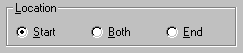
Location
Some features can be applied to the Start, End,
or Both ends of a shaft segment. The Start
is considered to be the left end of the shaft or segment as shown
in the Shaft dialogue box.
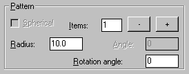
Pattern
Some features can be applied as a pattern, such as hole patterns.
It is similar to a polar array. When the pattern has more than one
item, the Angle: between items is required.
When a Tilt angle: and Radius:
is specified, Spherical coordinates can also
be used.
Position:
The position along the shaft can be specified. Features applied to
the start are measured from the left end, and move right. Features
applied to the end of the shaft are measured from the right end and
move left.
Radius:
A radius is used by patterns to specify a radial distance from the
center of the shaft to the feature.
Rotation angle:
Features can have a rotation angle relative to the shaft. Patterns
can be rotated as well as features such as gears, splines, and sprockets.
Tilt angle:
The tilt angle locates features in a radial pattern. An angle of 90
degrees orients the item perpendicular to the shaft.
Twist angle:
The twist angle rotates features so that the axis of the feature no
longer intersects the axis of the shaft.
Chamfer
A chamfer can be applied to the start or end of segments and recesses.
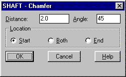
- Distance:
- This edit box sets the distance of the chamfer
measured horizontally along the recess or segment form start to end.
- Angle:
- This edit box sets the angle of the chamfer.
When the angle is negative or greater than 270 degrees, the chamfer
is added to the diameter. When the angle is less than 90 degrees,
the chamfer is subtracted from the diameter.
Data field
The Data field is non-graphical data that can be attached to an item.
This feature has a field name and a value. Field names that match
names of balloon attributes will be used by the BALLOON command and
APTLST command. Data fields named DESCP and DESCP2 will be used by
the LABEL command.
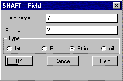
- Field name:
- This edit box sets the name of the data field.
- Field value:
- This edit box sets the value of the data field.
- Type
- This group of buttons sets the type of data
that will be entered.
Fillet
A fillet can be applied to the start or end of segments and recesses.
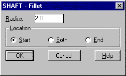
- Radius:
- This edit box sets the fillet radius. A positive
radius adds to the diameter. A negative radius subtracts from the
diameter.
Fix point
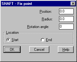
The Fix point feature is the insert point for the item. The position
lies along the Z axis. The rotation angle and radius specify the polar
coordinates in the XY plane.
Flat
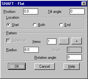
Flats can be applied externally on segments or internally on recesses.
Patterns of flats can be used to form polygon shaped features.
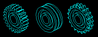
Gear
Gears can be applied externally on segments or internally on recesses.
Internal gears can also be applied through the length of a shaft.
Segments and recesses are automatically resized to fit the gear.
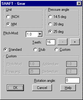
- Pressure angle
- This group of buttons sets the pressure angle
of the gear. Standard angles are listed. Custom angles can be entered
in the Custom group.
- Pitch/Mod:
- This pop-up list sets the pitch of the gear.
Inch gears use teeth per inch of diametral pitch. Metric gears use
the module system. Custom pitches can be entered in the Custom
group.
- Teeth:
- This group sets the number of gear teeth.
- Standard
- This button sets the gear to use standard
addendum and dedendum values. It cannot be set for gears with a non-standard
pitch or pressure angle.
- Stub
- This button sets the gear to use stub tooth
Addendum and Dedendum
values. It cannot be set for gears with a non-standard pitch or pressure
angle.
- Custom
- This button enables the Custom
group to allow setting of non-standard gear parameters. Addendum
and Dedendum values are ratios of the pitch.
Groove
Grooves for clips, retainers, and rings can be applied externally
to segments and internally to recesses. The groove is sized by selecting
a clip or other item from the HARDWARE dialogue box. See the HARDWARE
command for more information. You will be warned if the item does
not fit the current segment or recess.
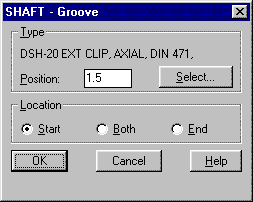
- Type
- This group shows the clip that will be used
in the groove, the position, and a select button. The minimum distance
to the edge of the segment is set automatically in the Position:
edit box when a new clip is selected.
Hardware
Hardware can be applied to shafts and segments. Hardware can be in
patterns, either axial or radial. The hardware is specified by selecting
from the HARDWARE dialogue box. See the HARDWARE command for more
information.
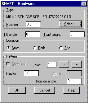
- Type
- This group shows the current hardware settings,
the position, and a select button.
Hole
Holes can be applied to shafts, segments, and recesses. Holes can
be in patterns, either axial or radial. The holes are specified by
selecting from the HOLE dialogue box. See the HOLE command for more
information.
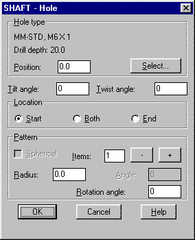
- Hole type
- This group shows the current hole settings,
the position, and a select button.
Keyway
Keyways can be applied externally to segments and internally to recesses.
The keyway is sized by selecting a key from the HARDWARE dialogue
box. See the HARDWARE command for more information.
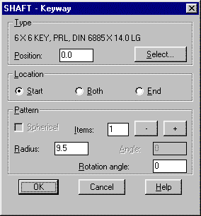
- Type
- This group shows the key that will be used
on the segment or recess, the position, and a select button. The position
is measured to the insert point of the key.
You will be warned if the key does not fit the current segment or
recess. The correct radius is set automatically when a key is selected.
The radius is measured to the insert point of the key.
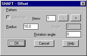
Offset
An offset or pattern of offset segments can be generated. Single offsets
can be used to create a crankshaft.
Pulley
A pulley can be applied to any segment. Segment length is automatically
set to fit the pulley. The current segment diameter and the recommended
range for the current pulley size is shown.
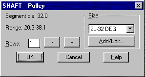
- Rows:
- This group sets the number of rows for the
pulley.
- Size
- This group contains a pop-up list to set the
size of the pulley.
- Add/Edit...
- This button displays the Edit Row dialogue
box for the current record in the pulley table.
Recess
Recesses are applied to shafts or segments. They can be used to form
webs on flywheels, gears, pulleys, and sprockets. They can also be
used to create through bores and internal tapers.

- Major
- This group controls the inside overall dimensions
of a recess.
- Minor
- This group controls the dimensions of a protrusion
from the center of a recess.
- Diameter:
- These two edit boxes set the diameters of
the major and minor dimensions. A minor diameter of 0.0 indicates
no minor dimensions.
- Taper angle:
- These two edit boxes set the taper angles
of the recess.
- Depth:
- This edit box sets the depth of the recess.
A depth of 0.0 indicates that the recess extends through the shaft
or segment.

Shaft
Shafts can be applied to shafts and segments as a feature. Shafts
can be in patterns, either axial or radial. The shafts are specified
by selecting from a SHAFT dialogue box. See the main SHAFT command
for more information.

- Type
- This group shows the current hardware settings,
the position, and a select button.
Sphere
A sphere can be applied to a segment. The sphere is automatically
fit to the segment size.

- Sphere diameter:
- This edit box sets the sphere diameter. The
segment is automatically resized to fit the sphere when a new value
is entered.
Spline
Splines can be applied externally on segments or internally on recesses.
Internal splines can also be applied through the length of a shaft.
Segments and recesses are automatically resized to fit the spline.
Inch and metric splines are included.

- Size
- This group contains a pop-up list to set the
size of the spline.
- Add/Edit...
- This button displays the Edit Row dialogue
box for the current record in the spline table.
Sprocket
A sprocket can applied to any shaft segment. Segments are automatically
resized to fit the sprocket.

- Heavy duty
- This toggle sets the row spacing for heavy
duty chains on some sizes of multi-row sprockets.
- Teeth:
- This group sets the number of sprocket teeth.
- Rows:
- This group sets the number of rows for the
sprocket.
- Size
- This group contains a pop-up list to set the
size of the sprocket.
- Add/Edit...
- This button displays the Edit Row dialogue
box for the current record in the sprocket table.
Thread
Threads can be applied externally on segments or internally on recesses.
Internal threads can also be applied through the length of a shaft.
Segments and recesses are automatically resized to fit the thread.
Inch and metric threads are included.

- Size
- This group contains a pop-up list to set the
size of the thread.
- Add/Edit...
- This button displays the Edit Row dialogue
box for the current record in the thread table.
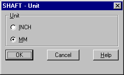
Unit
Units can be assigned to a shaft to insure the shaft is scaled correctly,
regardless of the current drawing unit setting. When exporting shafts,
units should always be assigned so that the shaft can be imported
correctly into drawings with different units.
The SYMCHG command can be used to change the shaft item at a later
time. See the SYMCHG and SYMUPD commands for more information.
The symbols are created as a single entity. If the symbol is exploded
it reverts back to the base entities. Once a symbol has been exploded
it cannot be edited with SYMCHG or SYMUPD.
See the following DPVAR variables that directly affect the SHAFT command.
ITEMALTD,
ITEMCLYR,
ITEMCLRH,
ITEMCTRL,
ITEMCTRM,
ITEMDSPL,
ITEMGEN,
ITEMHIDLIN,
ITEMTAND,
ITEMVIEW,
THREAD,
TOOTHMAX,
TOOTHSEG,
UNIT
CTRLINE Command
The CTRLINE (CenTeR LINE) command draws center lines and center marks
on hardware, hole, and shaft items.
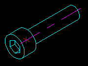
Command: ctrline
Select objects: Do so.
The ITEMCTRL and ITEMCTRM DPVAR variables control which centers will
be drawn. The centers are grouped with the items so that when an item
is changed, the centers will be updated.
See the following DPVAR variables that directly affect the CTRLINE
command.
ITEMCTRL,
ITEMCTRM
Group Editing of Items
Two commands are provided for grouping hardware and hole items by
size and type. Grouped items are automatically changed together when
any item in the group is changed. For instance, you might want to
have a nut and bolt change size whenever you change the size of a
corresponding hole. Both commands have the following prompt:
Select objects: Do so.
Any valid items in the selection set will be grouped.
The AutoCAD PICKSTYLE system variable controls how grouped items are
selected. If you want to select grouped items individually, PICKSTYLE
should be set to 0. Items that are grouped by size or type will still
be updated automatically.
GRPSIZE Command
The GRPSIZE (GRouP by SIZE) command will group selected hardware and
hole items so that when the size of one item is changed, SI Mechanical
will attempt to change the size of the other grouped items. If any
of the other items are not available in the specified size, the item
will not be changed.
GRPTYPE Command
The GRPTYPE (GRouP by TYPE) command will group selected hardware and
hole items so that when the type of one item is changed, SI Mechanical
will attempt to change the type of the other grouped items. If the
size of any of the other items is not available in the specified type,
the item will not be changed.
Global Editing of Items
Several commands are provided that will make changes to selection
sets of hardware, hole, and shaft items. For instance, you might want
to change all hardware in an assembly from one size to another or
from front view to an isometric view. These commands change the selected
items to match the current DPVAR variable settings. Each command has
the following prompt:
Select objects: Do so.
Any valid items in the selection set will be changed.
NEWLG Command
The NEWLG (NEW LenGth) command will change all hardware items that
have a variable length to the current setting of the HDWLG
DPVAR variable.
NEWSIZE Command
The NEWSIZE command will change all hardware and holes sizes to the
current setting of the ITEMSIZE DPVAR
variable. Only hardware and hole types that have a matching size in
the database will be changed. For instance, if ITEMSIZE was set to
".250-20 UNC", and you selected a DIN standard hardware, it would
not be changed. You would first have to change the hardware type using
the SYMCHG command.
NEWTYPE Command
The NEWTYPE command will change all hardware items to the current
setting of the HDWTYPE DPVAR variable and
all hole items to the current setting of the HOLETYPE
DPVAR variable. Only hardware and hole types that have a matching
size in the database will be changed.
NEWVIEW Command
The NEWVIEW command will change all hardware, hole, and shaft items
to the current setting of the ITEMVIEW
DPVAR variable.