Lesson Two - 3D Solid Model


This is one of several tutorials that give step-by-step examples of the various approaches to creating a drawing. Experiment with all methods to see what best suites your type of work.

In this session you will start SI Mechanical inside of AutoCAD and learn how to create a simple 3D solid model. The part is the same as that represented by the drawing in lesson one. This model will be used in lessons three and four. This session uses the pull-down menus primarily. Optionally, you can type the commands at the Command: prompt.

  1. Start SI Mechanical (see Starting SI Mechanical in the Getting Started section of this manual).
  2. Use the DPVAR command to set the UNIT DPVAR variable to MM.

Create Solid Part

You will now create a solid of a simple part. You will use SI Mechanical to add features to the part. The coordinates can be entered at the keyboard. Optionally, you can turn your coordinate display on and set the snap spacing to 5.0 allowing you to easily pick points on the screen.
  1. Use the AutoCAD PLINE command to draw the part profile:

    Command: pline
    From point: 0,0
    Arc/Close/Halfwidth/Length/Undo/Width/<Endpoint of line>: 60,0
    Arc/Close/Halfwidth/Length/Undo/Width/<Endpoint of line>: 60,20
    Arc/Close/Halfwidth/Length/Undo/Width/<Endpoint of line>: 20,20
    Arc/Close/Halfwidth/Length/Undo/Width/<Endpoint of line>: 20,40
    Arc/Close/Halfwidth/Length/Undo/Width/<Endpoint of line>: 0,40
    Arc/Close/Halfwidth/Length/Undo/Width/<Endpoint of line>: c

  2. Use the AutoCAD EXTRUDE command to extrude the profile into a solid.

    Command: extrude
    Select objects: Select profile.
    Path/<Height of Extrusion>: 20
    Extrusion taper angle <0>: 0

  3. Change the viewing angle with the AutoCAD VPOINT command.

    Command: vpoint
    Rotate/<View point>:<0.0,0.0,1.0>: r
    Enter angle in X-Y plane from the X axis <270>: 45
    Enter angle from X-Y plane <90>: 45
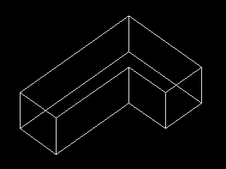
    3D view of part

Add Holes to Part

Use the HOLE command to add a countersunk hole and a tapped hole to the part.
  1. Select the pull-down menu labeled SI-MECH.
  2. Select the Symbols - Parts item in the menu.
  3. Select the Hole Options... item in the Symbols submenu.
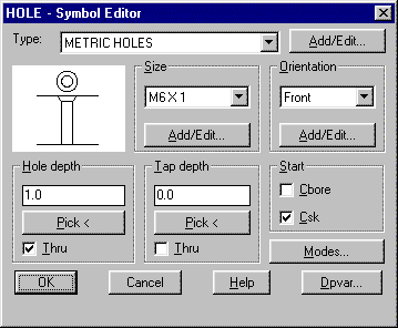
  4. The first hole will have these parameters: Type is METRIC HOLES, Size is M6 X 1, Start is Csk, Hole depth is 20.0 Thru, Orientation is Right. Set all options in the dialogue box to specify a hole according to the following figure:

    First hole settings

  5. Use the Modes... button to set the Model type to Solid.
  6. Pick the OK button to continue with the hole insertion.
  7. This is a solid view of a through hole projecting into the part. Enter the insert point:

    Solid, Left, MM-STD, M6 X 1, CSK, Drill thru
    Insert point <options>: 20,30,10
    Through point: 0,30,10

  8. Add another hole on the other leg of the part.
  9. Select the pull-down menu labeled SI-MECH.
  10. Select the Symbols - Parts item in the menu.
  11. Select the Hole Options... item in the Symbols submenu.
  12. Change options to have Csk off, and Tap depth to Thru. Enter the insert point:

    Solid, Bottom, MM-STD, M6 X 1, Drill thru, Tap thru
    Insert point <options>: 50,20,10
    Through point: 50,0,10

Save Part for Lessons Three and Four

Lesson Three and Lesson Four use this same part. Lesson Three requires that you leave the bracket and two holes as separate entities for now, so you will save it this way first. You will then subtract the holes from the bracket and save the part for Lesson Four.
  1. Save the part as lesson3.dwg.
  2. Use the AutoCAD SUBTRACT command to subtract the holes from the solid.

    Command: subtract
    Select solids and regions to subtract from...
    Select objects: Pick part.
    Select objects: [Enter]
    Select solids and regions to subtract...
    Select objects: Pick holes.
    Select objects: [Enter]

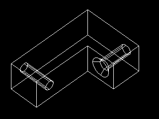
    Part with holes

  3. Save the drawing as bracket.dwg.