Lesson Three - Detailing a 3D Drawing


This is one of several tutorials that give step-by-step examples of the various approaches to creating a drawing. Experiment with all methods to see what best suites your type of work.

The solids.arx program must be loaded prior to starting SI Mechanical. The SOLVIEW and SOLDRAW commands will be used to create drawing views. In this session you will start SI Mechanical inside of AutoCAD and learn how to work on 3D drawings. The 3D solid part was saved in Lesson Two. This session uses the pull-down menus primarily. Optionally, you can type the commands at the Command: prompt.

  1. Start SI Mechanical (see Starting SI Mechanical in the Getting Started section of this manual).
  2. Open the drawing that you saved earlier, lesson3.dwg.

Setup The Drawing

You can setup your drawing by setting the units, scale, sheet size, and format.
  1. Run the SETUP command.
    1. Select the pull-down menu labeled SI-MECH.
    2. Select the Formats item in the menu.
    3. Select the Setup Options... item in the Formats submenu.
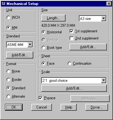
  2. Setup a drawing with these parameters: MM units, ASME-MM standard, Standard format, A3 size, Horizontal, Face sheet, 2:1 scale, check Pspace. Set all options in the dialogue box to specify a drawing according to the following figure:

    Setup parameters

  3. Pick the OK button and enter an insert point for the format.

    MM unit, 2.0 scale, ASME-MM standard, ASM000A3 format
    Insert point <options>: 0,0

    When you are presented with the Edit Attributes dialogue box, fill in the Company name and Drawn by fields.

Create Part Views

After setting up the drawing, you will be in paper space. You will create three views of the part using the AutoCAD SOLVIEW command.
  1. Create front view.

    Command: solview
    Ucs/Ortho/Auxiliary/Section/<eXit>: u
    Named/World/?/<Current>: w
    Enter view scale <1.0>: 2
    View center: 140,120
    View center: [Enter]
    Clip first corner: 70,70
    Clip other corner: 230,180
    View name: FRONT
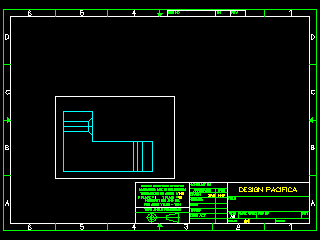
    Front view

  2. Create top view.

    Ucs/Ortho/Auxiliary/Section/<eXit>: o
    Pick side of viewport to project: Pick top edge of front view.
    View center: 140,220
    View center: [Enter]
    Clip first corner: 70,180
    Clip other corner: 230,260
    View name: TOP
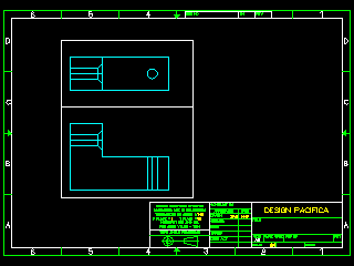
    Front and top views

  3. Create right view.

    Ucs/Ortho/Auxiliary/Section/<eXit>: o
    Pick side of viewport to project: Pick right edge of front view.
    View center: 280,120
    View center: [Enter]
    Clip first corner: 230,70
    Clip other corner: 320,180
    View name: RIGHT
    Ucs/Ortho/Auxiliary/Section/<eXit>: [Enter]
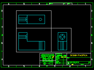
    Front, top, and right views

Add Center Lines

You will now use SI Mechanical to add center lines and center marks to the holes.
  1. Run the TAGMODES command to enable center lines.
    1. Select the pull-down menu labeled SI-MECH.
    2. Select the Symbols - Parts item in the menu.
    3. Select the Configure item in the Symbols - Parts submenu.
    4. Click on Draw center lines and Draw center marks.
  2. Run the CTRLINE command to draw center lines.
    1. Select the pull-down menu labeled SI-MECH.
    2. Select the Symbols - Parts item in the menu.
    3. Select the Modify item in the Symbols - Parts submenu.
    4. Select the Ctrline item in the Modify submenu.

    Select objects: Pick both holes in any view.

Add Annotation Tags

You will now use SI Mechanical to add several tags to the drawing. SI Mechanical allows you to put tags in model space or paper space. In this session, all tags will be placed in paper space.
  1. Run the TAG command to label the holes.
    1. Select the pull-down menu labeled SI-MECH.
    2. Select the Leader Tags item in the menu.
    3. Select the Label item in the Leader Tags submenu.
    4. Select the tapped hole in the right drawing view. Finish the prompt sequence to draw a leader pointing to the hole.

      Select object: Pick hole.
      Leader start: Pick point.
      To point: Pick point.
      To point: [Enter]
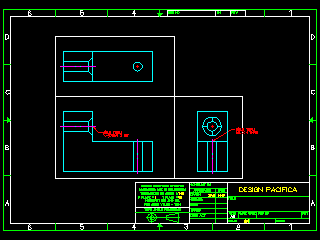
    5. Repeat the previous four steps for the countersunk hole in the main view.

      Labeled holes

      Now that the holes have been labeled they can be subtracted from the main solid.

  2. Switch to model space.

    Command: mspace

  3. Use the LYRSET command to set the object layer.
    1. Select the pull-down menu labeled SI-MECH.
    2. Select the Layer Utility item in the menu.
    3. Select the Lyrset item in the Layer Utility submenu.

      Select entity to set layer <options>: [Enter]

      The LYRSET dialogue box will be displayed.
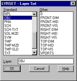
      LYRSET dialogue box

      Select the OBJ layer from the list box and pick the OK button. The OBJ layer will be set.

  4. Use the AutoCAD SUBTRACT command to subtract the holes from the part.

    Command: subtract
    Select solids and regions to subtract from...
    Select objects: Pick part.
    Select objects: [Enter]
    Select solids and regions to subtract...
    Select objects: Pick holes.
    Select objects: [Enter]

  5. Switch back to paper space.

    Command: pspace

  6. Run the TAG command to add a feature control symbol.
    1. Select the pull-down menu labeled SI-MECH.
    2. Select the Leader Tags item in the menu.
    3. Select the Geodim - FCF item in the Leader Tags submenu.
    4. Finish the prompt sequence to draw a leader pointing to the tapped hole in the top drawing view.

      Leader start: Pick point.
      To point: Pick point.
      To point: [Enter]
      Change symbol <N>: [Enter]
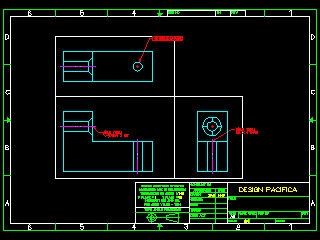
      Feature control frame added

  7. Use the TAGMODES command to set the arrow type to FOOT.
    1. Select the pull-down menu labeled SI-MECH.
    2. Select the Leader Tags item in the menu.
    3. Select the Configure... item in the menu in the Leader Tags submenu.
    4. Change the Arrow type: to foot.
  8. Run the TAG command to add datum feature symbols.
    1. Select the pull-down menu labeled SI-MECH.
    2. Select the Leader Tags item in the menu.
    3. Select the Geodim - DFS item in the Leader Tags submenu.
    4. Finish the prompt sequence to draw a leader pointing to the bottom surface of the main view.

      Leader start: 100,80
      To point: 100,70
      Change options <N>: Y
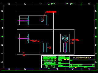
    5. Set the Datum: to A and Justify: to TC.
    6. Add another datum on a leader tag using 300,120 and 310,120 for the start and end point of the leader. Change the options to set the Datum: to B and Justify: to ML.
    7. Add another datum on a leader tag using 200,100 and 210,100 for the start and end point of the leader. Set the Datum: to C and Justify: to ML.
    8. Use the TAGMODES command to change the leader back to ARROW.

      Datum feature symbol added

  9. Run the TXTIN command to add notes.
    1. Select the pull-down menu labeled SI-MECH.
    2. Select the Text Utility item in the menu.
    3. Select the Import Text... item in the General submenu.
    4. Select the Import... button in the Text Editor dialogue box.
    5. Select general.txt from the file dialogue box.
    6. Pick the OK button in the Text Editor dialogue box.

      Justify/Style/<Start point>: 15,135

      Notes added

  10. Complete the drawing using AutoCAD commands to add the dimensions.
  11. Use the SOLDRAW command to render the viewports. Render only one viewport at a time.

    Command: soldraw
    Viewports to render...
    Select objects: Select front viewport.
    Select objects: [Enter]

    SOLDRAW will show all hidden lines even if there is a solid line in front of it. It may show up on the screen as a hidden line on top of a solid line but will still plot correctly. Optionally, you can erase the unwanted hidden lines.
  12. Repeat step ten for the top and then the right viewports. SOLDRAW can render more than one viewport at a time. However, only the last viewport selected will have the the correct layer colors and linetypes.
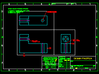
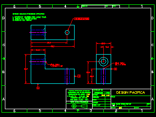
  13. Complete the drawing using AutoCAD commands to add the dimensions. The dimensions can be placed in paper space or model space. If you are placing dimensions in model space viewports, you should start the DIM command in that viewport. The dimensions will only be visible in the viewport where you start the DIM command. The following figure shows a completed drawing:

    Dimensioned drawing

    Turn off the VPORTS layer before plotting.