Lesson Four - 2D Views From a 3D Model
This is one of several tutorials that give step-by-step examples of the various
approaches to creating a drawing. Experiment with all methods to see what
best suites your type of work.
The solids.arx program must be loaded prior to starting SI Mechanical.
The MULTI2D and AUX2D commands will be used to create drawing views.
In this session you will start SI Mechanical inside of AutoCAD
and learn how to create 2D drawing views from a solid model. The 3D
solid part was saved in Lesson Two. This session uses the pull-down
menus primarily. Optionally, you can type the commands at the Command:
prompt.
- Start SI Mechanical (see Starting SI Mechanical
in the Getting Started section of this manual).
- Start a new drawing called lesson4.dwg.
You can setup your drawing by setting the scale, sheet size and format.
- Run the SETUP command.
- Select the pull-down menu labeled SI-MECH.
- Select the Formats item in the menu.
- Select the Setup Options... item in the Formats submenu.
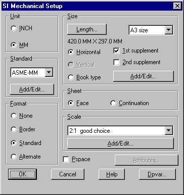
- Setup a drawing with these parameters: MM
units, ASME-MM standard,
Standard format, A3 size, Horizontal,
Face sheet, 2:1 scale. Set all options in the
dialogue box to specify a drawing according to the following figure:
- Pick the OK button and enter an insert point for the format.
MM unit, 2.0 scale, ASME-MM standard, ASM000A3 format
Insert point <options>: 0,0
When you are presented with the Edit Attributes dialogue
box, fill in the Company name and Drawn by fields.
After setting up the drawing, you will be in model space. You will
create four views of the part using the MULTI2D
command. The MULTI2D command creates 2D orthographic views from solid
models.
- Run the MULTI2D command to create the views.
- Select the pull-down menu labeled SI-MECH.
- Select the Drawing Views item in the menu.
- Select the Multi View Setup item in the Formats submenu.
Current drawing/DWG file/SAT file/<DWG>: [Enter]
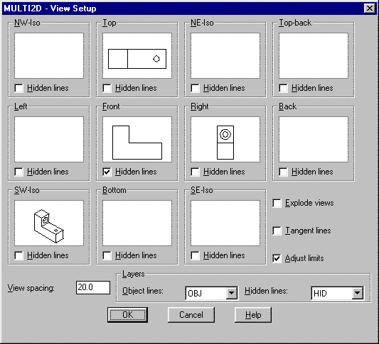
Select bracket.dwg from the file dialogue box. Set the following
MULTI2D options: Front, Top,
Right, and SW Iso views
selected, Front, Hidden lines
checked, View spacing is 20. Set all options
in the dialogue box according to the following figure:
- Pick the OK button and enter insert points for orthographic and isometric views.
Position - ortho views <done>: 60,45
Position - ortho views <done>: [Enter]
Position - iso views <done>: 10,10
Position - iso views <done>: [Enter]

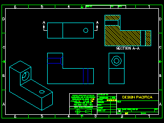
You can create auxiliary and section views with the AUX2D
command. The AUX2D command creates 2D views from solid models or from
MULTI2D views as long as the original solid model is available.
- Run the AUX2D command to create the views.
- Select the pull-down menu labeled SI-MECH.
- Select the Drawing Views item in the menu.
- Select the Auxiliary/Section item in the Formats submenu.
First point on plane: 55,115
Second point on plane: 125,115
Continue/Flip/<options>>: c
Insert point: 165,115
Insert point <done>: [Enter]
Section letter <A>: [Enter]
The AUX2D and MULTI2D commands provide an easy way to create 2D views
from 3D solid models. The resulting 2D views have no model intelligence.
They are simple 2D blocks. SI Mechanical can create hardware,
hole, and shaft items directly as intelligent 2D ojects. This is the
preferred method of creating 2D views for these items.