Lesson Five - Creating a Flange
This is one of several tutorials that give step-by-step examples of the various
approaches to creating a drawing. Experiment with all methods to see what
best suites your type of work.
In this session you will use the SHAFT command to create a 3D model
of a flange. You can also create the flange as a 2D or wire frame
model, but not all features will appear if direct generation is used.
This session uses the pull-down menus primarily. Optionally, you can
type the commands at the Command: prompt.
- Start SI Mechanical (see Starting SI Mechanical
in the Getting Started section of this manual).
- Use the DPVAR command to set the UNIT DPVAR variable to MM.
You will now create a solid shaft with five segments. The entire part
will be created in one operation after all segments and features are
specified.
- Use the SHAFT command to create the part:
- Select the pull-down menu labeled SI-MECH.
- Select the Shaft Options... item in the menu. The shaft
dialogue box will be displayed.
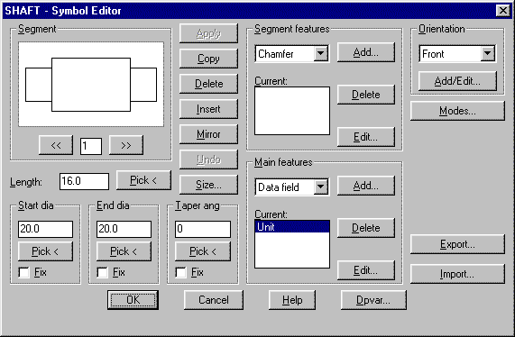
- Pick the Insert button until there
are five segments shown in the Segment image.
Use the < and > buttons to move along the shaft.
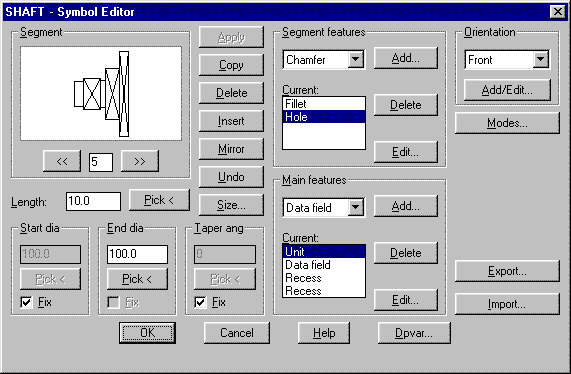
- Use the edit boxes to set the segment dimensions. Segments
will be set according to the following dimensions:
| Segment | Length | Start dia | End dia |
| 1 | 10.0 | 30.0 | 30.0 |
| 2 | 20.0 | 36.0 | 36.0 |
| 3 | 6.0 | 32.0 | 32.0 |
| 4 | 16.0 | 60.0 | 60.0 |
| 5 | 10.0 | 100.0 | 100.0 |
- Add a Data field to the Main features Current:
list. Main features apply to the entire shaft. The Data field will
have these Major parameters: Field
name is DESCP, and Field
value is FLANGE. Type is String.
Pick OK.
- Add a Recess to the Main features Current:
list. Main features apply to the entire shaft. The recess will have
these Major parameters: Location
is Start, and Diameter:
is 20.0. All other parameters, including Depth:,
are 0.0. A depth of 0.0 indicates a through recess. Pick OK.
- Add another Recess to the Main features
Current: list. The recess will have these Major
parameters: Location is End, Diameter:
is 44.0, and Depth: is 16.0.
All other parameters are 0.0. Pick OK.
- Move to segment two and add a thread to the Segment features
Current: list. Segment features apply to individual
segments. The thread will be a Millimeter thread
with a Size: of M36 X 4. Pick the Threads...
button and set the threads to Detailed. Pick
OK. The segment is automatically sized to fit
the selected thread.
- The threaded segment will have a chamfer at the start
and end of the thread. Add a chamfer to the Segment
features Current: list for segment two. The chamfer will have
these parameters: Location is Both,
Distance: is 1.5, and Angle:
is 45. Pick OK.
- Move to segment four and add a fillet to the Segment
features Current: list. The fillet will have these parameters:
Location is Start, and
Radius: is -6.0. A negative radius causes a
reduced diameter fillet as opposed to an increased diameter fillet.
Pick OK.
- Move to segment five and add a fillet to the Segment
features Current: list. The fillet will have these parameters:
Location is Start, and
Radius: is -3.0. Pick OK.
- Add a hole pattern to the Segment features
Current: list for segment five. Select a hole with these parameters:
Location is Start, Type
is METRIC HOLES, Size is M6 X 1, Start is
Cbore, and Hole
depth is 10.0 Thru. The Pattern will have
these parameters: Items
are 6, Radius: is 40.0, Angle:
is 60, and Rotation angle: is 0. Pick OK.
- Set the View to Solid, pick OK, and insert the part.
Command: shaft
Solid, Front, 5 segment(s), 6 feature(s)
Insert point <options>: 210,160
<Rotation angle>/Reference: [Enter]
- Change the viewing angle with the AutoCAD VPOINT command.
Command: vpoint
Rotate/<View point>:<0.0,0.0,1.0>: r
Enter angle in X-Y plane from the X axis <270>: 45
Enter angle from X-Y plane <90>: 35
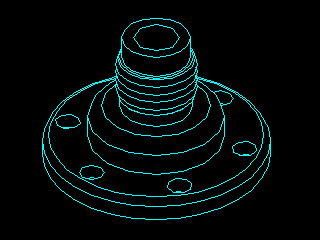
Save this drawing as flange.dwg to use in Lesson Six. You
can use the SYMCHG command to make changes to the part.