Drawing Setup
You can setup your drawing to conform to ASME, ISO,
or other standards. It should be done prior to any dimensioning and
drawing annotation. The standard determines the size of dimension
text, arrow heads, and other annotation features in a drawing. SI Mechanical's
SETUP command will set all of these for you to insure that subsequent
text and dimensions are to the correct standard.
You can use SI Mechanical to setup 2D views from solid models
and create enlargements from 2D views.
SETUP Command
The SETUP command sets up a drawing according to units, scale, standard,
and format type and size.
Command: setup
MM unit, 1.0 scale, ASME-MM standard, ASM000A3 format
Insert point <options>: Pick point.
The command line shows the current settings. The settings can be changed
by responding with [Enter] to the insert point prompt. A dialogue
box similar to the following figure will be displayed:
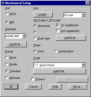
- Unit
- This pair of buttons sets the drawing units.
You can choose either INCH or MM.
If you want to change units to something else, you should change the
setting of the UNIT DPVAR variable as well
as any other variables and then run the SETUP command from the command
line without entering new options.
- Standard:
- This pop-up list sets the drafting standard.
The standards are specified in the STANDARD table (see Database
Tables in the Customizing section of this manual).
- Add/Edit...
- These three buttons display the Edit Row dialogue
box for the current record in the standard, format, or scale table.
- Format
- This group of buttons sets the format type.
You can choose any one of the four buttons. None
will setup the drawing without a format but to the correct size. Border
will setup the drawing with a single line border running around the
drawing limits. Standard
will determine which group of formats and drawing scales to choose
from, and annotation parameters. Alternate
will cause a search for a selected format with the prefix set by the
ALTFMT DPVAR variable. If no alternate format
is found a standard format is drawn instead.
- Size
- This group contains a pop-up list of available
sizes. The list of sizes can be different for different standards.
Some sizes are available in various lengths enabling the Length...
button. The Horizontal,
Vertical, and Booktype
buttons only apply to some format sizes. The 1st
and 2nd supplement check boxes control the optional
title block supplements on some formats.
- Sheet
- This pair of buttons sets either the Face
or Continuation type
sheet.
- Scale:
- This pop-up list sets the scale of your final
drawing. You have your choice of standard drawing scales. The scales
are specified in a scale table associated with each drafting standard
list in the STANDARD table (see Database Tables in the
Customizing section of this manual). If you want to use a
different scale, you can change the setting of the DWGSCALE DPVAR variable
before you run the SETUP command. See Pspace below for
plotting scale.
- Pspace
- This check box determines if the format will
be in paper space or model space. The
drawing will normally be plotted at full scale if this box is checked.
Otherwise you will plot at the scale chosen from the Scale:
pop-up list
- Attributes...
- This button displays the Edit Attributes dialogue
box for the current drawing format. You can use it to change information
in the title block. The AutoCAD DDATTE command can
also be used to edit attributes.
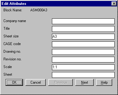
SETUP automatically establishes drawing limits, dimension
variables, text height, line scales, and other drawing parameters.
You choose a format, it is inserted, and a dialogue box is displayed
to fill in the remaining title block information.
The SYMCHG command can be used at any time to change the format size,
type or scale. Any information in the current title block that is
usable in the new one is transferred so that you won't have to
refill the new title block. Parts lists and revision blocks are
also transferred.
Multiple sheets can be setup in the same file by repeating the SETUP
command and picking a new insert point. Sheets must not overlap each
other. The setup will be based on the following DPVAR variable settings:
ALTFMT, DWGSCALE, FORMAT, STANDARD, UNIT
Annotation Scale
Unlike manual drafting, the drawing scale setting does not indicate
the scale that you draw at. Except in special cases, you will draw
at full scale. SI Mechanical will utilize the DWGSCALE
setting differently, depending on the TILEMODE
setting and whether model space or paper space is being used.
Drawing scale affect
| TILEMODE | SPACE | Scaling |
| 0 | PSPACE | All annotation symbols, dimensions, and text are drawn at full scale. |
| 0 | MSPACE | All annotation is drawn at a scale based on the inverse of the current viewport scale. |
| 1 | MSPACE | All annotation is drawn at a scale based on the inverse of the DWGSCALE DPVAR variable. |
Drawing Scale
You should normally draw all parts and assemblies at full scale. The
exception is when you are working in 2D model space
and have to show a detail or view at a different scale than the rest
of the drawing. When you work in paper space, you can
show views at different scales even if your parts are created at full
scale.
2D versus 3D
Even though there are no restrictions in AutoCAD, it is generally
easier to annotate 2D drawings in model space and 3D models in paper
space. You may encounter exceptions based on special drawing requirements,
and it is possible to create 2D drawings from 3D models (see AUX2D
and MULTI2D commands).
APTLST Command
The APTLST (Automatic ParTs LiST) command uses information in the
balloons (see BALLOON and TAG commands) to create a parts list on a formatted drawing. If balloons with
duplicate item numbers are found, the text in the first balloon is
used in the parts list. Quantities in duplicate balloons are totaled
in the parts list. Any prior parts list is deleted.
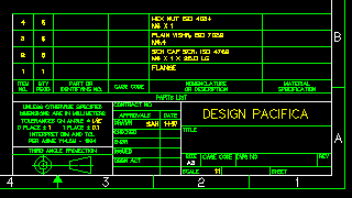
Command: aptlst
Balloons to process...
Select objects: Do so.
If no drawing sheet is active, you will be prompted to select one.
The AutoCAD COPY, DDATE, ERASE, and MOVE commands can modify the
parts list.
PTLST Command
The PTLST (ParTs LiST) command lets you add to a drawing's parts list by
inserting a single parts list block at the next available location in the
table.
Command: ptlst
A dialogue box is displayed to fill in the necessary information.
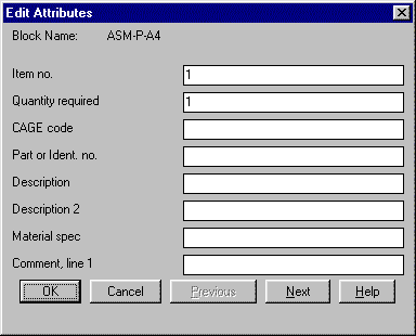
The AutoCAD COPY, DDATE, ERASE, and MOVE commands can modify the
parts list.
REVS Command
The REVS (REViSion) command lets you add to a drawing's revision
table by inserting a revision block at the next
available location in the table.

Command: revs
A dialogue box is displayed to fill in the necessary information.
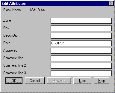
The AutoCAD COPY, DDATE, ERASE, and MOVE commands can modify the
revision block.
SETSHT Command
The SETSHT (SET SHeeT) command sets the active drawing sheet. Since
more than one sheet can exist in a drawing, one sheet must be active
to perform commands such as APTLST, PTLST, and REVS that operate on
a particular drawing format.
Command: setsht
Select sheet: Do so.
See the following DPVAR variables that directly affect the SETSHT
command:
SHTSET
DPSHOWACT Command
The DPSHOWACT (Design Pacifica SHOW ACTive) command highlights the
active sheet in a drawing (see SETSHT command).
Command: dpshowact
AUX2D Command
The AUX2D (AUXiliary 2D view) command projects a 2D orthographic view
off of a solid model in the current drawing. The view can be a partial
section, full section, or full view.
Composite sections can be created where only some parts in an assembly
are sectioned. Views can also be projected from MULTI2D views when
the original solid is available.
Command: aux2d
First point on plane: Pick point.
Second point on plane: Pick point.
The line between the two points defines a perpendicular plane for
viewing the solid. When the plane crosses one or more solids, it acts
as a cutting plane for section views. When the plane does not cross
any solids, then the view can only be an auxiliary view and you will
be prompted to select the solids to use for the view projection:
Select objects: Do so.
From the main prompt you can Continue, Flip the view direction, or
display and change the view options. If you enter Flip, the view direction
will be reversed. When you enter Continue, the command will continue
using the current option settings. The default option settings draws
an auxilary view from solids that are not crossed, or a full section
from solids that are crossed.
Continue/Flip/<options>:
The settings can be changed by responding with [Enter] to the main
prompt. A dialogue box similar to the following figure will be displayed:
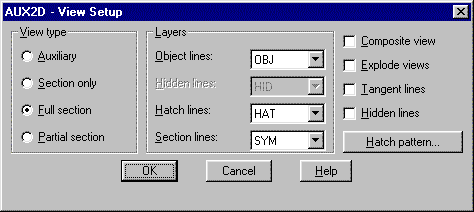
- View type
- This group specifies the type of view to draw.
- Auxiliary
- This button indicates a full view projected
from the selected solids. None of the section options will be available.
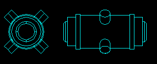
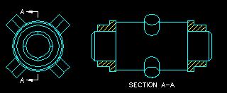
- Section only
- This button indicates a section projected
from the selected solids with no background object lines shown.
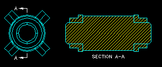
- Full section
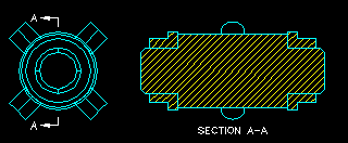
- This button indicates a full section projected
from the solids crossed by the cutting plane with all background object
lines shown.
- Partial section
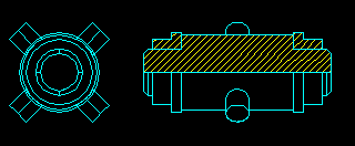
- This button indicates a partial section projected
from the selected solids with all background and unsectioned forground
object lines shown. You will be prompted to select which solids you
want in the view.
Items in view...
Select objects: Do so.
- The section begins at the first point picked
on the cutting plane and extends only in the direction of the second
point.
- Layers
- This group specifies the layers to use for
the different types of lines in the projected draw.
- Composite view
- This toggle indicates a composite view where
some of the solids used in the view projection will not be sectioned
even if the cutting plane intersects them. You will be prompted to
select which solids you want sectioned.
Items to section...
Select objects: Do so.
- All selected solids will be used in the view
projection. Only solids that are crossed by the cutting plane and
selected for sectioning will be sectioned.
- Explode views
- This toggle indicates that the view will be
composed of individual entities rather than a block.
- Tangent lines
- This toggle indicates that tangent lines will
be drawn on projected views. For instance, an edge that shows the
transition between a fillet and a straight side can be displayed or
not.
- Hidden lines
- This toggle indicates that hidden lines will
be drawn on projected views.
- Hatch pattern...
- This button displays the SI Mechanical
hatch pattern dialogue box. The hatch pattern used for section views
can be set. See the PHATCH command.
MULTI2D Command
The MULTI2D (MULTIple 2D views) command projects 2D orthographic and
isometric views off of a solid model. The solid model can be in the
current drawing or an external file.
Command: multi2d
Current drawing/DWG file/SAT file/<DWG>:
If you respond with DWG or SAT, a file dialogue box is displayed.
When more then one solid is available, you will be prompted to select
the solids to use. You can select one or more solids to use in the
views.
Select objects: Do so.
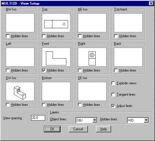
There are eleven view groups. Each view group has an image button
that acts as a toggle to select or disable the view. The Hidden
lines toggle in each view group indicates hidden lines will
be drawn for that view.
- Explode views
- This toggle indicates that the views will
be composed of individual entities rather than a block.
- Tangent lines
- This toggle indicates that tangent lines will
be drawn on all views. For instance, an edge that shows the transition
between a fillet and a straight side can be displayed or not.
- Adjust limits
- This toggle indicates that the drawing limits
will be expanded to encompass the views as they are positioned. This
will insure that the drawing views are always visible as they are
placed.
- View spacing
- This edit box specifies the distance between
the edge of a view and the edge of any adjacent views. The default
distance is equal to the snap spacing.
- Layers
- This group specifies the layers to use for
the different types of lines in the projected views.
When you pick the OK button you will be prompted
to enter insert points for orthographic and isometric views. A view
matrix for the orthographic views shows the bounding box for each
view as you position them. You can keep picking new points until the
views are in the desired positions. A second view matrix is displayed
to position the isometric views.
Position - ortho views <done>: Pick point.
Position - ortho views <done>: [Enter]
Position - iso views <done>: Pick point.
Position - iso views <done>: [Enter]
Once the views are positioned, they will be created and placed in
the drawing.
DETAIL Command
The DETAIL command creates an enlargement
of a specified area of a 2D drawing. It also labels the detail and
the enlargement with the detail name and scale factor.
Command: detail
Detail name <default>: Enter letter.
Center of detail area: Pick point.
Radius point: Pick point.
Radius point <OK>:
Relative scale factor <default>: Enter scale.
Center of scaled detail: Pick point.
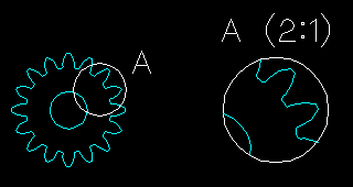
The radius point indicates the point on the detail radius where the
detail letter will appear. You can keep picking a new point until
it appears in a satisfactory position, then press [Enter].
The relative scale factor specifies how much to enlarge
the detail, but is not the same as the final scale. If you specify
a relative scale factor of 2.0 and the drawing scale is 5/1, the final
plotted scale of the enlargement will be 10/1.
Text entities that lie partially outside the enlargement radius will
not be included in the enlargement. Solid filled areas that lie partially
outside the enlargement will show up as line boundaries. Attributes
are ignored.