Support Files
This section describes the SI Mechanical drawing templates,
menu, and the SI Mechanical text fonts.
SI Mechanical Drawing templates
SI Mechanical includes several drawing templates. The templates
have standard dependent variables and styles preset to make drawing
in a particular standard easier. It is possible to mix drafting standards
in a single drawing, but you will have to set the dimension variables
as needed. SI Mechanical includes the following drawing templates:
- SIASMIN
- ASME inch defaults
- SIASMMM
- ASME metric defaults
- SIDINMM
- DIN metric defaults
- SIISOMM
- ISO metric defaults
- SIJISMM
- JIS metric defaults
The drawing templates are in the SI Mechanical directory.
You can use the AutoCAD PREFERENCES command to make it easier to locate
the drawing templates. (see Tips - Drawing templates in the
Getting Started section of this manual).
You can set the drawing template when you start a new drawing by using
the Use a Template button in the NEW command dialogue box.
SI Mechanical Menu
SI Mechanical has specific menu files. The menu files can be
merged with other menus. The SI Mechanical toolbar, pull-down,
and tablet menus allow quick access to all of the features of SI Mechanical.
The SI Mechanical pull-down menu occupies one of the positions
on the pull-down menu bar.
SI Mechanical Toolbar menus
SI Mechanical has a main toolbar menu with flyouts for other toolbars.
Other toolbars can also be placed on the screen for easy access. The
DPTBARS command is used to show or hide the various toolbars.
- SI-Mechanical

- SI-Alpha

- SI-Format

- SI-Views

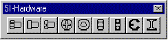
- SI-Hardware
- SI-General

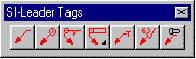
- SI-Leader Tags
- SI-Geodim

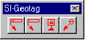
- SI-Geotag
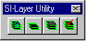
- SI-Layer Utility
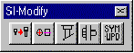
- SI-Modify
SI-MECH Pull-down Menu

- Load SI Mechanical
- Loads SI Mechanical. SI Mechanical can
be configured to load automatically.
- DPhelp...
- Runs the DPHELP command. Displays the DPHELP dialogue box.
- Symbol Change
- Runs the SYMCHG command. Edits various SI Mechanical
symbols.
- Drawing Views
- Switches to the Drawing Views submenu. See
Drawing Views Pull-down Submenu for explanation of options.
- Formats
- Switches to the Formats submenu. See Formats
Pull-down Submenu for explanation of options.
- General
- Switches to the General submenu. See General
Pull-down Submenu for explanation of options.
- Layer Utility
- Switches to the Layer Utility submenu. See
Layer Utility Pull-down Submenu for explanation of options.
- Leader Tags
- Switches to the Leader Tag submenu. See Leader
Tags Pull-down Submenu for explanation of options.
- Symbols - Annotate
- Switches to the Symbols - annotate submenu. See Symbols -
annotate Pull-down Submenu for explanation of options.
- Symbols - Parts
- Switches to the Symbols - parts submenu. See
Symbols - parts Pull-down Submenu for explanation of options.
- Text Utility
- Switches to the Text Utility submenu. See
Text Utility Pull-down Submenu for explanation of options.
- XY Dimension
- Switches to the XY Dimension submenu. See
XY Dimension Pull-down Submenu for explanation of options.
- Alpha (use w/text)...
- Displays a toolbar of alpha characters
such as degree, countersink, and counterbore symbols.
This menu returns the ASCII characters required to access this symbol.
- Toolbars...
- Runs the DPTBARS command. Displays a dialogue
box to show or hide the various SI Mechanical toolbar menus.
- Edit Database...
- Runs the DBEDIT command. Displays the DBEDIT dialogue box. Used to
view and edit the database tables.
Drawing Views Pull-down Submenu
This submenu lists commands to create drawing views.

- Auxiliary/Section
- Runs the AUX2D
command. Draws an auxiliary or section view from solids or a MULTI2D
view. Full section views are labeled.
- Detail Enlargement
- Runs the DETAIL
command. Creates an enlarged copy of a detail in a drawing and labels it.
- Multi View Setup
- Runs the MULTI2D command. Draws a matrix of selected orthographic
and isometric 2D views from solids.
Formats Pull-down Submenu
This submenu lists commands and features for detailing your drawing.

- Setsht
- Runs the SETSHT command. Makes a sheet active in a multiple
sheet drawing.
- Show Active
- Runs the DPSHOWACT command. Highlights the active sheet in
a multiple sheet drawing.
- Setup
- Runs the SETUP command. Sets up a drawing with default units,
sheet type, sheet size, scale, and title block.
- Setup Options...
- Displays the SETUP dialogue box to setup a drawing. The default
setup can be changed.
- Part List - Automatic
- Runs the APTLST command. Generates a parts list on a formatted
drawing from information in balloon tags.
- Part List - Single
- Runs the PTLST command. Adds one part to the parts list on a
formatted drawing.
- Revision Block
- Runs the REVS command. Adds one revision block to the revision
list on a drawing.
- BOM...
- Runs the AutoCAD DDATTEXT command. Writes out a bill of materials
text file from selected balloons or part list items.
General Pull-down Submenu
This submenu contains insertion and parametric type routines to speed
the drawing process.

- 2Dbox
- Runs the 2DBOX command. Draws a rectangle.
- Basicdim
- Runs the BASICDIM command. Changes dimension text into a basic dimension.
- Conversion Table
- Runs the CNVTABLE command. Draws a conversion table for dimensions.
- Detail Block
- Inserts a detail block. Example: DETAIL A
- Dpvar...
- Runs the DDPVAR command and displays the DPVAR variable dialogue box.
- Extension Line
- Runs the EXLINE command. Draws an extension line between two points.
- Limit Line
- Runs the LIMLINE command. Draws a line between two points and
extends that line to the limits of the drawing. The limits are
defined by the AutoCAD LIMITS command.
- Long Break
- Runs the LONGBRK command. Inserts a break symbol indicating a
part break on a long line.
- Macro
- Runs the MACRO command. Combines a sequence of commands into a
temporary user-defined command.
- Phatch
- Runs the PHATCH command. Hatches an enclosed area with one pick.
- Proto Stamp
- Inserts a PROTOTYPE ONLY stamp block.
- Quote Stamp
- Inserts a QUOTATION ONLY stamp block.
- Section Block
- Inserts a section block. Example: SECTION A-A
- Section Line
- Runs the SLINE command. Draws a section line with section
letters and arrow heads.
- Shaft Break
- Runs the SHFTBRK command. Draws a round-shaft break symbol.
- Slot
- Runs the SLOT command. Draws an oblong slot.
- Table
- Runs the TXTTABLE command. Draws a text table with user definable
rows and columns.
- Thread...
- Runs the HARDWARE command with the THREAD category. Draws a
threaded section.
- View Block
- Inserts a view block. Example: VIEW A
Layer Utility Pull-down Submenu
This submenu contains general command for creating, deleting and setting
layers.

- Dialogue
- Runs the AutoCAD DDLMODES command. Displays the layer dialogue box.
- Lyrchg
- Runs the LYRCHG command. Moves (changes) picked entities from one
layer to another.
- Lyrdel
- Runs the LYRDEL command. Deletes everything on a layer by picking
an entity.
- Lyrlst
- Runs the LYRLST command. Creates (makes) a layer chosen from the
layer table dialogue box.
- Lyroff
- Runs the LYROFF command. Turns off a layer by picking an entity.
- Lyrset
- Runs the LYRSET command. Sets a layer by picking an entity.
- ON *
- All layers are turned on.
- OFF *
- All layers are turned off except the current one.
Leader Tags Pull-down Submenu
This submenu sets different leader types and attaches one of many
different items at the end of the leader.

- Configure...
- Runs the TAGMODES command. Sets the leader type and balloon placement.
- Balloon
- Runs the TAG command. Draws a leader with a Balloon.
- Renumber
- Runs the BALLNUM command. Renumbers selected balloons sequentially.
- Geodim-DFS
- Runs the TAG command. Draws a leader with
a Datum Feature Symbol from defaults.
- Geodim-DTS
- Runs the TAG command. Draws a leader with
a Datum Target Symbol from defaults.
- Geodim-FCF
- Runs the TAG command. Draws a leader with
a Feature Control Symbol from defaults.
- Geodim-PTS
- Runs the TAG command. Draws a leader with
a Projected Tolerance zone Symbol from defaults.
- Label
- Runs the TAG command. Draws a leader with
a label for a selected piece of hardware or a hole.
- Surface
- Runs the TAG command. Draws a leader with
a surface finish symbol from defaults.
- Text
- Runs the TAG command. Draws a leader with
single or multiple lines of text.
- Weld
- Runs the TAG command. Draws a leader with
a welding symbol from defaults.
- XYZ Point
- Runs the TAG command. Draws a leader followed
by an XYZ point dimension at the end of the leader.
Symbols - Annotate Pull-down Submenu
This submenu contains symbol modify commands and insertion commands
for GEODIM, SURFDIM, and WELDIM symbols.

- Symchg
- Runs the SYMCHG command. Edits various SI Mechanical
symbols.
- Symupd
- Runs the SYMUPD command. Updates selected SI Mechanical
symbols.
- Geodim
- Runs the GEODIM command. Inserts a Geometric Tolerance Symbol
with the default settings.
- Geodim Options...
- Switches to the Geodim submenu. See Geodim
Options Pull-down Submenu for explanation of options.
- Surfdim
- Runs the SURFDIM
command. Inserts a surface finish symbol with the default settings.
- Surfdim Options...
- Displays the SURFDIM dialogue box.
- Weldim
- Runs the WELDIM
command. Inserts a welding symbol with the default settings.
- Weldim Options...
- Displays the WELDIM dialogue box.
Geodim Pull-down Submenu
This submenu allows the user to set the default setting for GEODIM.

- Feature Control
- Runs the GEODIM
command. Displays the feature control frame dialogue box
- Datum Target
- Runs the GEODIM
command. Displays the datum target dialogue box.
- Datum Feature
- Runs the GEODIM
command. Displays the datum feature dialogue box.
- Projected Tolerance
- Runs the GEODIM
command. Displays the projected tolerance zone dialogue box.
Symbols - Parts Pull-down Submenu
This submenu contains symbol modify commands and insertion commands
for hardware, hole, and shaft items.

- Configure...
- Runs the ITEMODES
command. Sets modes that control creation of items.
- Modify
- Switches to the Modify submenu. See Modify
Symbols Pull-down Submenu for explanation.
- Hardware
- Runs the HARDWARE
command. Inserts a hardware item based on default settings.
- Hardware Options...
- Displays the HARDWARE dialogue box.
- Hole
- Runs the HOLE
command. Inserts a hole based on the default settings.
- Hole Options...
- Displays the HOLE dialogue box.
- Shaft Generator
- Runs the SHAFT
command. Inserts a shaft based on default settings.
- Shaft Options...
- Displays the SHAFT dialogue box. The default
shaft can be changed.
Modify Symbols - Parts Pull-down Submenu
This submenu contains symbol modification commands for hardware, hole,
and shaft items.

- Ctrline
- Runs the CTRLINE
command. Adds center lines and center marks on hardware, hole, and
shaft items.
- Holeclip
- Runs the HOLECLIP
command. Clips the end of a hole side view at an angle.
- Itemclip
- Runs the ITEMCLIP
command. Clips out a section of an item in a two dimensional view.
- Symchg
- Runs the SYMCHG
command. Edits various SI Mechanical symbols.
- Symupd
- Runs the SYMUPD
command. Updates selected SI Mechanical symbols.
- Group by size
- Runs the GRPSIZE
command. Groups hardware and hole items together by size.
- Group by type
- Runs the GRPTYPE
command. Groups hardware items together by type.
- Set to Current Length
- Runs the NEWLG
command. Updates length of selected hardware to match the
HDWLG DPVAR variable.
- Set to Current Size
- Runs the NEWSIZE
command. Updates size of selected hardware and hole items to match
the ITEMSIZE DPVAR variable.
- Set to Current Type
- Runs the NEWTYPE
command. Updates type of selected hardware and holes to match the
HDWTYPE and HOLETYPE
DPVAR variables.
- Set to Current View
- Runs the NEWVIEW
command. Update selected items to match the ITEMVIEW
DPVAR variable.
Text Utility Pull-down Submenu
This submenu provides access to the text editor and text manipulation
commands.

- Edit text
- Runs the TXTEDIT
command and displays the text editor dialogue box to edit text in
the drawing.
- Import text...
- Runs the TXTIN
command and displays the text editor dialogue box to insert new text
into the drawing.
- Txthight
- Runs the TXTHIGHT
command. Changes the height of selected text entities.
- Txtjust
- Runs the TXTJUST
command. Changes the justification of selected text entities.
- Txtstyle
- Runs the TXTSTYLE
command. Changes the style of selected text entities.
- Txttable
- Runs the TXTTABLE
command. Draws a table of text in rows and columns.
- Txtwidth
- Runs the TXTWIDTH
command. Changes the width factor of selected text entities.
XY Dimension Pull-down Submenu
This submenu provides access to SI Mechanical datum dimensioning
commands.

- Automatic
- Runs the AXYDIM
command. Automatic dimensioning of a part.
- AXYdim Options...
- Runs the AXYDIM
command and displays the AXYDIM dialogue box.
- XYtable
- Runs the XYTABLE
command. Automatically dimension a series of holes and draws a cross
reference table.
- XYtable Options...
- Runs the XYTABLE
command. Displays the XYTABLE dialogue box.
- XYdim
- Runs the XYDIM
command. Manual XY dimensioning.
- X
- Runs the XYDIM
command. Dimensions an X coordinate.
- Y
- Runs the XYDIM
command. Dimensions a Y coordinate.
- Zero
- Runs the XYDIM
command. Sets the Zero point.
SI-MECH Tablet menu
The SI Mechanical tablet menu area is located in the upper area
of the AutoCAD tablet menu. The SI Mechanical tablet overlay
is designed to work with the standard AutoCAD tablet overlay. The
tablet menu is not required but it can enhance productivity. See the
following figure of the SI Mechanical tablet menu overlay.
@TBLFIGANCHOR = <$&TABLET[-]>
SI Mechanical Text Fonts
SI Mechanical defines a text style called SI-MECH that contains
geometric tolerancing and drafting symbols. You can use the AutoCAD
STYLE command to change the default font files used by SI Mechanical.
You can also define a style called GEODIM that uses the GDTSYM bigfont
as an alternate. This will allow you to attach a different bigfont
to the SI-MECH style. Fonts that use the IGES geometric tolerancing
character set (iges1003.shx and gdt.shx) do not support
the new geometric tolerancing standard.
- GDTSYM
- The bigfont used by SI Mechanical for
geometric tolerancing and drafting symbols.
- SI-MECH
- Standard character set font matching the style
of the GDTSYM font.