Utility Commands
This section covers SI Mechanical commands that allow you to
access the help facility, modify your menu file, and make changes
in your drawing. Things that can be changed include text, drafting
symbols, formats, and layers. Commands for adding various construction
features are also included.
DPHELP Command
You can use the DPHELP (Design Pacifica HELP) command to find information
about any of the SI Mechanical commands, variables, and program
features. You can reach the DPHELP facility at the Command: prompt
or from any SI Mechanical dialogue box that contains a Help...
button.
The DPHELP command format is:
Command: dphelp
The HELP dialogue box has a Help button that
explains the usage of the DPHELP command.
DPMODMNU Command
The DPMODMNU (Design Pacifica MODify MeNU) command is used to merge
the SI Mechanical menus with a menu of your choice.
Command: dpmodmnu
The main SI Mechanical toolbar will be visible. You can
load the SI Mechanical pill-down menu by using the AutoCAD
menuload command.
DPTBARS Command
The DPTBARS (Design Pacifica ToolBARS) command is used to show (activate)
or hide the various SI Mechanical toolbar menus. This command
only works with menus that have the SI Mechanical toolbars in
the menu file. The DPMODMNU command can be used to add the toolbars
to your existing menu if the DPTBARS command does not work.
Command: dptbars
A dialogue box similar to the following figure is displayed:
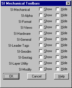
- Show
- This check box will show (activate) the associated
toolbar.
- Hide
- This check box will hide the associated toolbar.
- SI-Mechanical
- Main SI Mechanical toolbar.
- SI-Alpha
- Alphanumeric drafting symbols.
- SI-Format
- Drawing formats and setup.
- SI-Views
- Drawing view creation.
- SI-Hardware
- Common hardware categories.
- SI-General
- General purpose utilities.
- SI-Leader Tags
- Leaders with annotation tags.
- SI-Geodim
- Geometric tolerancing symbols.
- SI-Geotags
- Geometric tolerancing leaders.
- SI-Layer Utility
- Layer manipulation utilities.
- SI-Modify
- Symbol change and editing utilities.
SI-Mechanical toolbar gives you access to
the other toolbars even if they have not been shown (activated).
SYMCHG Command
The SYMCHG (SYMbol CHanGe) command is used to edit items created by
GEODIM, HARDWARE, HOLE, PHATCH, SETUP, SHAFT, SURFDIM, and WELDIM.
It works on blocks with attributes in the same manner
as the AutoCAD DDATTE command. It operates on
other entities in the same manner as the AutoCAD CHPROP
command. SYMCHG can be invoked at the end of the GEODIM, SURFDIM,
and WELDIM commands by responding with [Y] to the change symbol prompt.
Command: symchg
Select object: Do so.
The appropriate dialogue box or prompt is displayed.
Changing Formats
If the selected item is a drawing border or format inserted by SETUP, a dialogue box is displayed allowing you to
change the item.
Changing Geometric Tolerancing Symbols
If the selected symbol was created by GEODIM, one of several different
dialogue boxes is displayed depending on the type of geometric tolerancing symbol.
Most options are screened to insure that valid input is supplied.
Any selection that is not valid will be grayed out. An exception to
this is the optional modifier which is a string the user enters. If
you change a feature control
frame and the geometric symbol, invalid options are screened out.
Required settings are added. The invalid or required settings for
each geometric symbol are contained in the Geodim rule base (see GEODIM
database table).
Changing Hardware
If an item created by HARDWARE is selected, a dialogue box is displayed
allowing you to change the item.
Changing Hatch Patterns
If a hatched area is selected, a dialogue box is displayed allowing
you to change the pattern, size, or angle. If the area is not fully
bounded or the scale is inappropriate, the area will fail to hatch.
Changing Holes
If an item created by HOLE is selected, a dialogue box is displayed
allowing you to change the item.
Changing Shafts
If an item created by SHAFT is selected, a dialogue box is displayed
allowing you to change the item.
Changing Surface Finish Symbols
If an item created by SURFDIM is selected, a dialogue box is displayed
allowing you to change the item.
Changing Welding Symbols
If an item created by WELDIM is selected, a dialogue box is displayed
allowing you to change the item.
Changing Other Entities
If the selected item is a block with attributes, the
Edit Attributes dialogue box is displayed. If the selected item is
not recognized by SYMCHG and has no attributes, the AutoCAD DDMODIFY
command will be applied. This will also happen if the extended data
from an SI Mechanical symbol has been removed or incorrectly
altered.
SYMUPD command
The SYMUPD (SYMbol UPDate) command updates items created by GEODIM,
HARDWARE, HOLE, PHATCH, SETUP, SHAFT, SURFDIM, and WELDIM. It also
works on AutoCAD dimension entities
exactly like the AutoCAD DIM UPDATE command. It ignores all other
entities.
Command: symupd
Select objects: Do so.
The objects are redrawn to reflect the current settings of applicable
DPVAR variables and AutoCAD system variables.
Editing SI Mechanical Database Tables
Most aspects of SI Mechanical are controlled by tables in the
SI Mechanical database. You can alter or enhance the way that
the program works by editing these tables. As an example, you could
use it to add custom hardware sizes or modify the layer tables.
DBEDIT Command
The DBEDIT (DataBase EDIT) command allows you to view and modify the
SI Mechanical database. See the DBWRITE
DPVAR variable to enable writes to the database.
DBEDIT first displays the Edit Table dialogue box allowing you to
select a database table, select a row, and modify columns. The Edit
Table dialogue box is similar to the following figure:
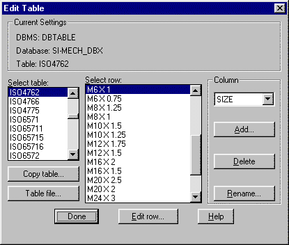
- Select table:
- This list box sets a table from the standard
tables included in the SI Mechanical library.
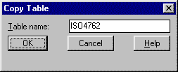
- Copy table...
- This button displays the Copy Table dialogue
box. A new table name can be entered to copy an existing table to
a separate file. The dialogue box is similar to the following figure:
- Table file...
- This button displays a standard file dialogue
box entitled Select Table File. You can select any table that exists
as a separate file.
- Select row:
- This list box sets a row in the current table.
- Column
- This group contains a pop-up list to set the
column that will display field values in the list of rows. The default
column is the first column in the database. Only rows that have a
unique value will be displayed in the row list.
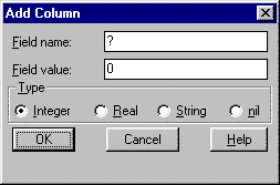
- Add...
- This button displays the Add Column dialogue
box. You can add a new column to the table by entering a column name,
field value, and type. The dialogue box is similar to the following
figure:
- Delete
- This button deletes the current column from
the table.
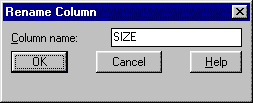
- Rename...
- This button displays the Rename Column dialogue
box. You can change the name of the current column in the table by
entering a new column name. The dialogue box is similar to the following
figure:
- Edit row...
- This button displays the Edit Row dialogue
box for the row selected in the Select row:
list. The dialogue box is similar to the following figure:
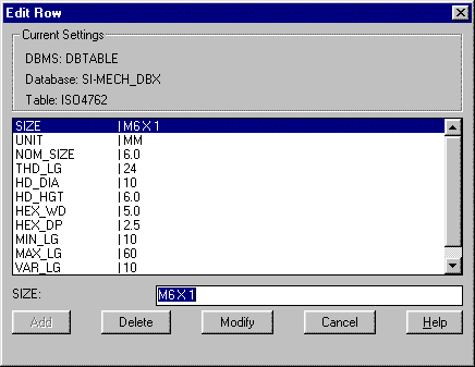
You can enter a new value for the current field in the edit box. You
can pick a new field to edit from the list box. If the DBWRITE
DPVAR variable is set to 0, you can view the row but you will not
be able to make any changes.
- Add
- This button adds a new row to the current
table. If the key value for the current row is not unique, the button
will be grayed out.
- Delete
- This button deletes the current row from the
current table.
- Modify
- This button modifies the current row in the
current table.
SI Mechanical System Variables
DPVAR Command
The SI Mechanical DPVAR (Design
Pacifica VARiables) command behaves almost exactly like the AutoCAD
SETVAR command. The DPVAR drawing variables provide default values
and control the operation of many of the SI Mechanical commands.
SI Mechanical saves the values in a collection of variables stored
in the drawing, and provides a method for you to examine and change
these variables directly.
The DPVAR command lets you access the DPVAR variables. To examine
and possibly change a DPVAR variable, enter this command:
Command: dpvar
Variable name or ?:
Listing DPVAR variables
You can request a list of variables and their current settings by
entering ?. SI Mechanical displays this prompt:
Variable(s) to list <*>:
Enter a variable name or a wild card pattern. See also Wild-Card
Characters in the AutoCAD Command Reference for further
information.
Changing Values for DPVAR Variables
Some DPVAR variables cannot be changed; these are flagged in the output
by the legend (read only) following the value. If you enter the name
of a variable that is not read only, you receive the prompt:
New value for variable-name <current>:
The current value of the variable is shown. If you respond to this
prompt by pressing [Enter] or [Esc], the variable is left unchanged.
If you enter a valid new value, the variable's value is changed
accordingly.
If the named variable is read only, its current value is displayed
as follows:
variable-name = current (read only)
For example, if the current drawing standard is "ASME"
and you want to set it to "ISO", you can do so with
the DPVAR command:
Command: dpvar
Variable name or ?: standard
New value for STANDARD <"ASME">: iso
SI Mechanical remembers the last variable name used in the DPVAR
command in the current editing session, and offers it as the default
for subsequent DPVAR commands. This reduces needless typing when referencing
the same variable sequentially.
DDPVAR Command
The DDPVAR (Dialogue Design Pacifica VARiables) command accesses the
DPVAR variable dialogue box. It is also accessible from inside many
of the other SI Mechanical dialogue boxes by picking the Dpvar...
button. The DDPVAR dialogue box is similar to the following figure:
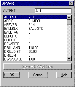
You can enter a new value for the current variable in the edit box.
You can pick a new variable to edit from the list box.
- Save to DPVAR table
- This button writes all DPVAR variables in
the current drawing to the DPVAR table. See the DBWRITE
DPVAR variable to enable writes to the database.
RFDPVAR Command
The RFDPVAR (ReFresh Design Pacifica VARiables) command refreshes
all DPVAR variables in the current drawing. This is required if you
customize the DPVAR data file by adding new variables and you want
to load those variables into an existing SI Mechanical drawing
without effecting any other variable settings. RFDPVAR might also
be required if a future update to SI Mechanical uses any new
DPVAR variables.
Command: rfdpvar
RSDPVAR Command
The RSDPVAR (ReSet Design Pacifica VARiables) command resets all DPVAR
variables in the current drawing to reflect the defaults in the DPVAR
data file.
Command: rsdpvar
Layer Utilities
SI Mechanical includes a set of commands for manipulating layers.
The commands can be used on any layer that exists in the drawing or
any SI Mechanical layer even if it has not been created yet.
LYRCHG Command
The LYRCHG (LaYeR CHanGe) command lets you move entities from one
layer to another. Pick objects to be moved, then specify the layer
to which they should be moved by picking any entity on the destination
layer.
Command: lyrchg
Select objects: Pick objects.
Select entity to specify layer <options>: Pick entity.
If you press [Enter], LYRCHG displays a dialogue box similar to the
following figure:
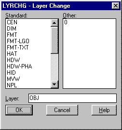
You can enter a new layer name in the Layer:
edit box or pick one from one of the two lists. The layer that you
enter must be present in one of the lists.
LYRDEL Command
The LYRDEL (LaYeR DELete) command deletes all entities on the layer
you specify by picking any entity on that layer.
Command: lyrdel
Select entity to delete layer <options>: Pick entity.
If you press [Enter], LYRDEL displays a dialogue box similar to the
following figure:
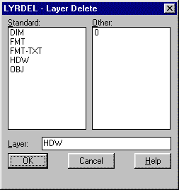
You can enter a layer name in the Layer: edit
box or pick one from one of the two lists. The layer that you enter
must be present in one of the lists.
After a layer is specified, the following prompt is displayed:
Delete entities from layer: layer name
Continue? <N>:
If you answer Y, all items on the specified layer will be deleted.
LYRLST Command
The LYRLST (LaYeR LiST) presents a dialogue box of all layers in the
current layer definition file.
Command: lyrlst
LYRLST displays a dialogue box similar to the following figure:
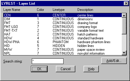
You can select a layer listed in the dialogue box to make it the current
layer.
- Search string:
- This edit box restricts the selection of layers
to the match string that you enter.
- Add/Edit...
- This button displays the Edit Row dialogue
box for the current record in the layer definition table
LYROFF Command
The LYROFF (LaYeR OFF) command turns off the layer you specify by
picking any entity on that layer.
Command: lyroff
Select entity to turn layer off <options>: Pick entity.
If you pick an entity on the current layer an additional prompt is
presented.
Really want layer (name) (the CURRENT layer) off? <N>
If you press [Enter], LYROFF displays a dialogue box similar to the
following figure:
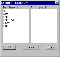
Picking a layer in the on list will move the layer to the off list.
Picking a layer in the off list will move the layer to the on list.
LYRSET Command
The LYRSET (LaYeR SET) command sets the layer you specify by picking
any entity on that layer.
Command: lyrset
Select entity to set layer <options>: Pick entity.
If you press [Enter], LYRSET displays a dialogue box similar to the
following figure:
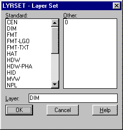
You can enter a layer name in the Layer: edit
box or pick one from one of the two lists. The layer that you enter
must be present in one of the lists.
LIMLINE Command
The LIMLINE (LIMit LINE) command will draw a line that extends to
the drawing limits. A single through point and rotation
angle must be specified.
Command: limline
Position of line: Pick point.
Angle of line: Enter angle.
MACRO Command
The MACRO command lets you combine a sequence of commands as a user
defined command.
Command: macro
Enter macro name <default>:
After you type [Enter], you are in the macro recording mode. Enter
the sequence of commands and point selections you want to save as
a macro. All entries must be either from the keyboard or point picks.
Menu picks are not allowed. Press [Ctrl-Q] when done.
To execute the macro itself, type the macro name at the Command: prompt.
The macro only remains active for the current drawing session.
Text Editing Utilities
Many functions in SI Mechanical require that you edit single
or multiple lines of text. A common text editor is displayed in a
dialogue box by these commands. The text editor is similar to the
following figure:

Some functions may be grayed out depending on the editing operation.
The Line number edit box displays the current line of text to be edited.
You can edit other lines of text by picking the line from the list
box. You must press [Enter] to enter any text in the edit box.
- Clear
- This button clears all text from the current
editing session.
- Copy
- This button copies the current line of text
to memory.
- Delete
- This button deletes the current line of text.
- Insert
- This button adds a new line above the current
line.
- Paste
- This button adds any text copied to memory
to the end of the current line.
- Sort
- This button sorts the lines of text alphabetically.
- Undo
- This button will undo the last operation.
You cannot undo the export operation.
- Uppercase
- This button converts the current line of text
to upper case.
- Lowercase
- This button converts the current line of text
to lower case.
- Export...
- This button displays the standard file dialogue
box so that you can indicate a file name. All text in the editor will
be written to the file.
- Import...
- This button displays the standard file dialogue
box so that you can indicate a file name. All text in the file will
be read into the text editor.
- Search
- This button searches for the next occurrence
of the text string entered in the Search for:
edit box.
- Replace
- This button replaces any occurrence found
with the Search button with text in the Replace
with: edit box.
TXTEDIT Command
The TXTEDIT (TeXT EDIT) command lets you edit existing text in a drawing
by selecting multiple lines.
Command: txtedit
Select objects: Do so.
After you select the text, TXTEDIT displays the SI Mechanical
text editor.
TXTHIGHT Command
The TXTHIGHT (TeXT HeIGHT) command lets you change the height
of selected text in a drawing.
Command: txthight
New text height <default>:
Select objects: Do so.
After you select the text, TXTHIGHT will convert it to the new height.
TXTIN Command
The TXTIN (TeXT INsert) command lets
you enter multiple lines of text for insertion into a drawing.
Command: txtin
TXTIN displays the SI Mechanical text editor. After composing
the text in the editor, the following prompt is presented:
Justify/Style/<Start point>:
The justification, style, and start point can be specified.
TXTJUST Command
The TXTJUST (TeXT JUSTification) command lets you change the justification
of selected text in a drawing.
Command: txtjust
New justification, Center/Left/Middle/Right/TL/TC/TR/ML/MR/<Left>:
Select objects: Do so.
After you select the text, TXTJUST will convert it to the new justification.
TXTSTYLE Command
The TXTSTYLE (TeXT STYLE) command lets you change the style of selected text in a drawing.
Command: txtstyle
New text style (or ?) <default>:
Select objects: Do so.
If you respond with [?] when asked for a new style, all styles in
the current drawing will be listed on the text screen. After you select
the text, TXTSTYLE will convert it to the new style.
TXTWIDTH Command
The TXTWIDTH (TeXT WIDTH) command lets you change the width
of selected text in a drawing.
Command: txtwidth
New width factor <default>:
Select objects: Do so.
After you select the text, TXTWIDTH will convert it to the new width.
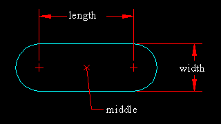
SLOT Command
The SLOT command draws an oblong slot according to the insertion point,
length, width, and rotation angle you supply.
Command: slot
Middle of slot: Pick point.
Length of slot: Enter value.
Width of slot: Enter value.
Rotation angle: Enter angle.